Video encoding/decoding device, method, and program

a video encoding and decoding technology, applied in the field of video encoding/decoding devices, can solve the problems of difference in compression efficiency, increase transmission delay, and difference in prediction efficiency, and achieve the effect of reducing display delay

Active Publication Date: 2015-06-25
NEC CORP
View PDF10 Cites 5 Cited by
  • Summary
  • Abstract
  • Description
  • Claims
  • Application Information

AI Technical Summary

Benefits of technology

[0039]According to the present invention, when a video decoding device receives and replays a bitstream generated by a video encoding device in the middle thereof, partial display can be started until a synchronization completed picture, thereby reducing display delay.

Problems solved by technology

In the case of using the adaptive predictive coding method, due to a difference in correlation between pictures, a difference in prediction efficiency is caused.
Consequently, a difference in compression efficiency is caused.
However, it is a problem that the instantaneous refresh increases transmission delay.
The increase of capacity of the buffer memory causes an increase in transmission delay between the encoding device and the decoding device.
Therefore, the instantaneous refresh is not appropriate for a use requiring high real-time property, such as equipment remote control through a video.

Method used


Image

  • Video encoding/decoding device, method, and program
  • Video encoding/decoding device, method, and program
  • Video encoding/decoding device, method, and program

Examples


first exemplary embodiment

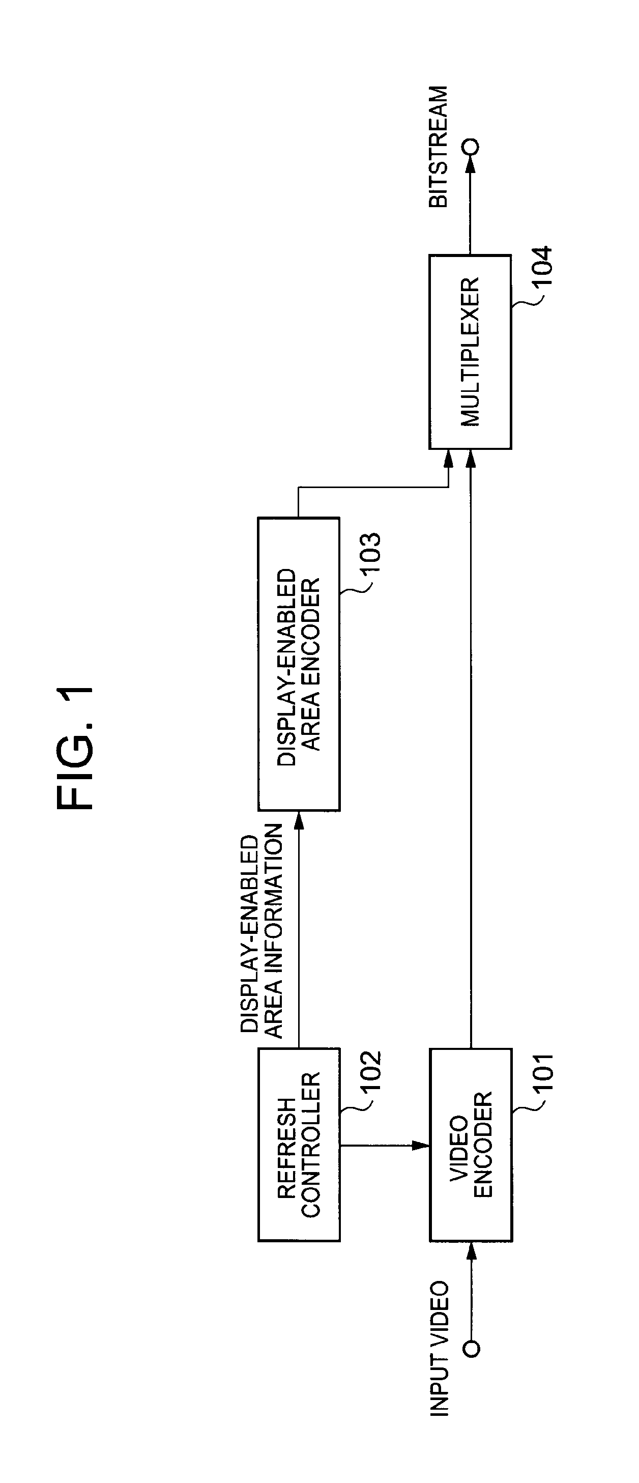
[0058]FIG. 1 is a block diagram of a video encoding device according to a first exemplary embodiment of the present invention. As illustrated in the drawing, the video encoding device of the first exemplary embodiment includes a video encoder 101, a refresh controller 102, a display-enabled area encoder 103, and a multiplexer 104. The present exemplary embodiment is characterized in that the display-enabled area encoder 103 which encodes display-enabled area information of each picture obtained from the refresh controller 102 for supplying to the multiplexer 104.

[0059]The video encoder 101 performs encoding on each of pictures in an input video and supplies a bitstream of the video to the multiplexer 104.

[0060]When an adaptive predictive coding is performed in the video encoder 101, the refresh controller 102 supplies a control signal to the video encoder 101 such that prediction restriction is kept between refreshing groups of segments so as to perform intended refresh. The refresh...

example

[0071]A specific example of the video encoding device of the above first exemplary embodiment will be described below.

[0072]In the present example, with respect to a progressive video in which a spatial resolution for each frame is 320×240 pixels, the most left area of 64×240-pixel areas obtained by uniformly dividing a picture by 5 in a horizontal direction is set as an intra-coded segment, and refresh is performed so that an intra-coded segment is shifted so as not to be overlapped with each other through 5 pictures.

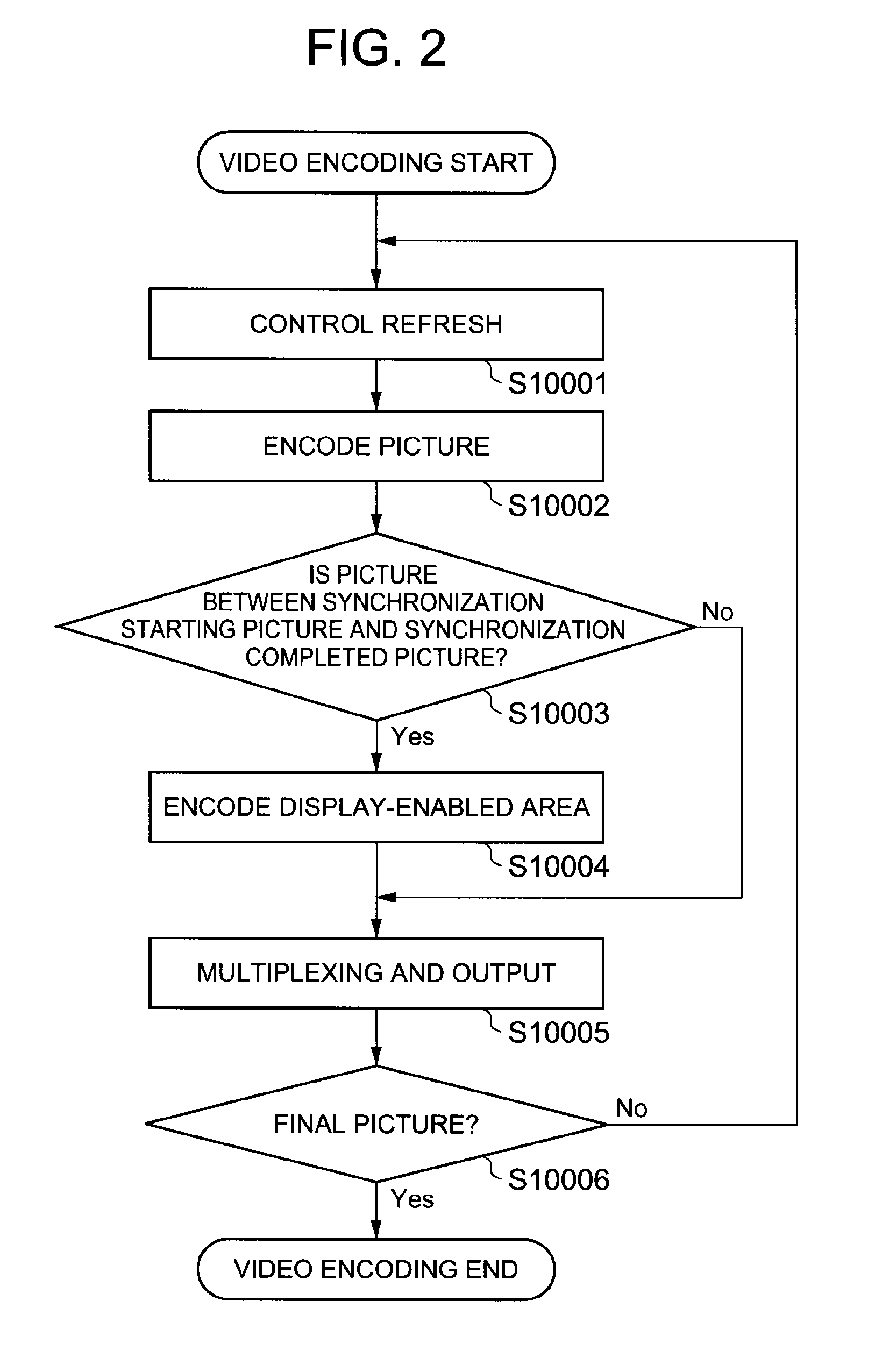
[0073]FIG. 3 illustrates a specific case where refresh is performed. In FIG. 3, a picture P (ti) at time ti is assumed as a synchronization starting picture, and P(ti+4) is assumed as a synchronization completed picture. A refresh completion segment in the picture P(t) at time t indicates an area set as an intra-coded segment one time from time ti to time t. In this case, respective display-enabled areas of pictures P (ti), P (ti+1), P (ti+2), P (ti+3) and P (ti+4) are...

second exemplary embodiment

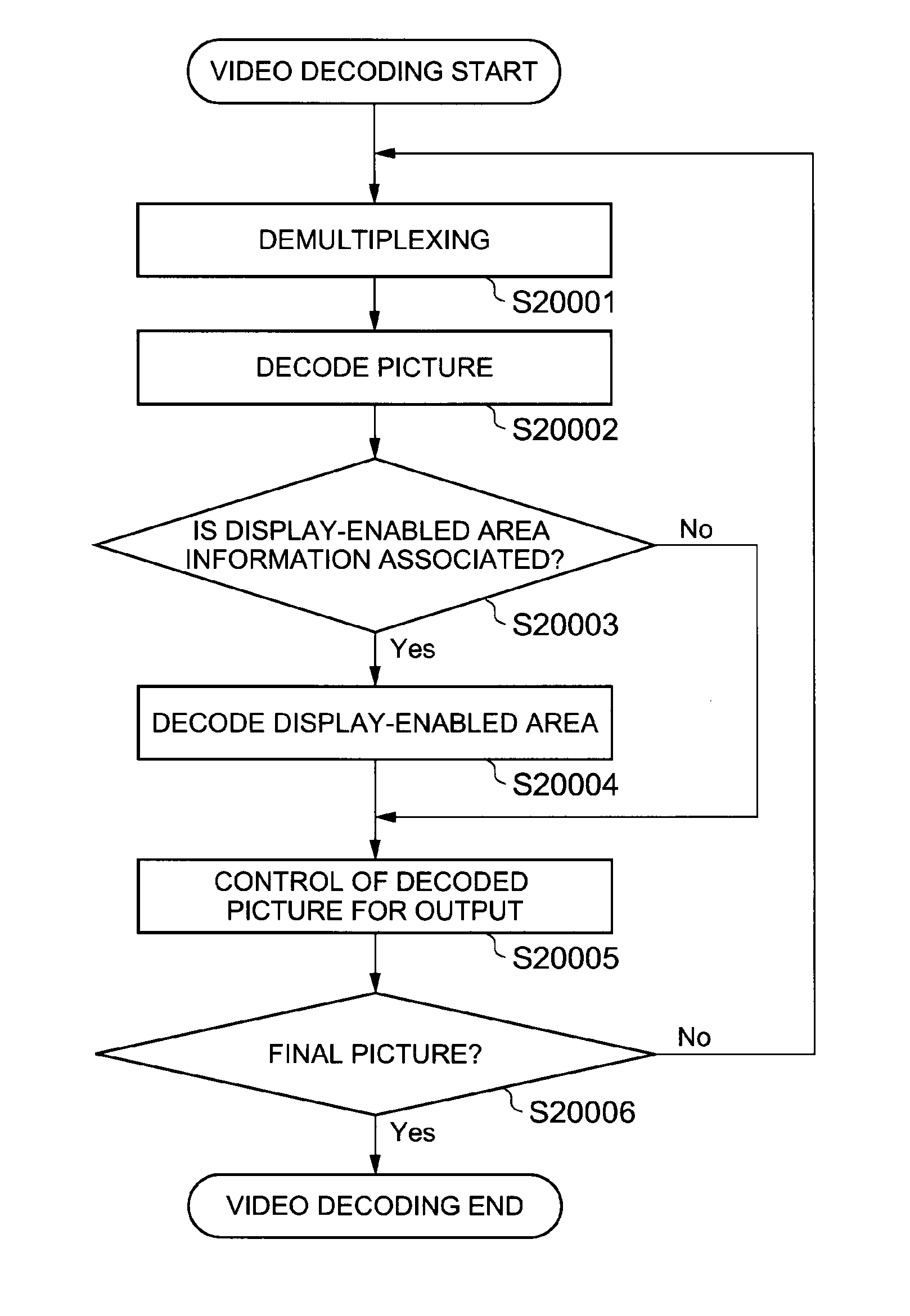
[0105]FIG. 8 is a block diagram of a video decoding device according to a second exemplary embodiment of the present invention. As illustrated in FIG. 8, the video decoding device of the second exemplary embodiment includes a demultiplexer 201, a video decoder 202, a display-enabled area decoder 203, and a video output controller 204. The present exemplary embodiment is characterized in that the display-enabled area decoder 203 that decodes and outputs information of a display-enabled area in each picture is provided, and the video output controller 204 that interprets the display-enabled area and performs control such that a decoded image other than the display-enabled area is not output is also provided.

[0106]The demultiplexer 201 demultiplexes a bitstream, extracts a video bitstream and a display-enabled area information bitstream, and supplies the video bitstream to the video decoder 202, and supplies the display-enabled area information bitstream to the display-enabled area dec...


PUM


Abstract

A video encoder 101 encodes image data of an input moving image based on prediction and generates a video bitstream of encoded pictures. A refresh controller 102 refreshes such that a partial area in the picture is assumed as a unit area to be refreshed and the unit area to be refreshed is moved on a picture-by-picture basis. A display-enabled area encoder 103 encodes a display-enabled area for each picture and generating a display-enabled area information bitstream in refreshing. A multiplexer 104 multiplexes the video bitstream and the display-enabled area information bitstream.

Description

TECHNICAL FIELD[0001]The present invention relates to a video coding technology, in particular, a video coding technology using adaptive predictive coding, which performs compression by adaptively switching intra-picture coding and inter-picture predictive coding.BACKGROUND ART[0002]A video has a large amount of information, therefore it is necessary to perform compression encoding of the video with high efficiency when the video is recorded and transmitted as digital data. In order to realize high-efficiency compression, various elemental technologies are used for video compression encoding.[0003]There is a predictive coding technology as one of the elemental technologies for video compression encoding. The predictive coding technology is a technology for, when respective pixels in a video are sequentially encoded, generating a predicted value of a pixel to be currently encoded by using one or a plurality of temporally and / or spatially neighboring pixels and encoding a differential...

Claims


Application Information

Patent Timeline
Patent Type & Authority Applications(United States)
IPC IPC(8): H04N19/68H04N19/44H04N19/50
CPCH04N19/68H04N19/44H04N19/50H04N19/105H04N19/107H04N19/159H04N19/167H04N19/174H04N19/196H04N19/70H04N19/503H04N19/59
Inventor AOKI, HIROFUMICHONO, KEIICHITSUKADA, MASATO
Owner NEC CORP
Why Eureka
Try Eureka