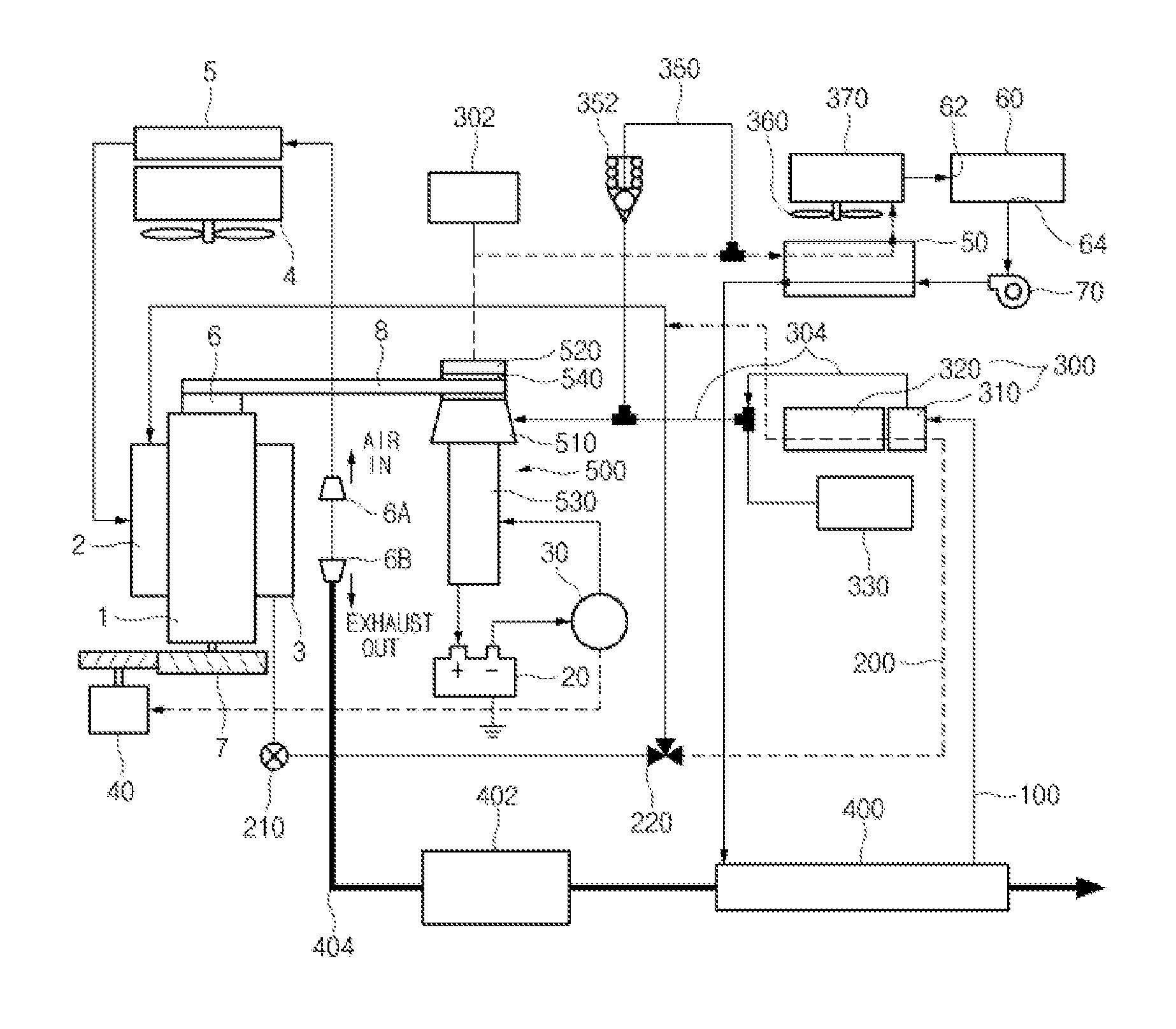
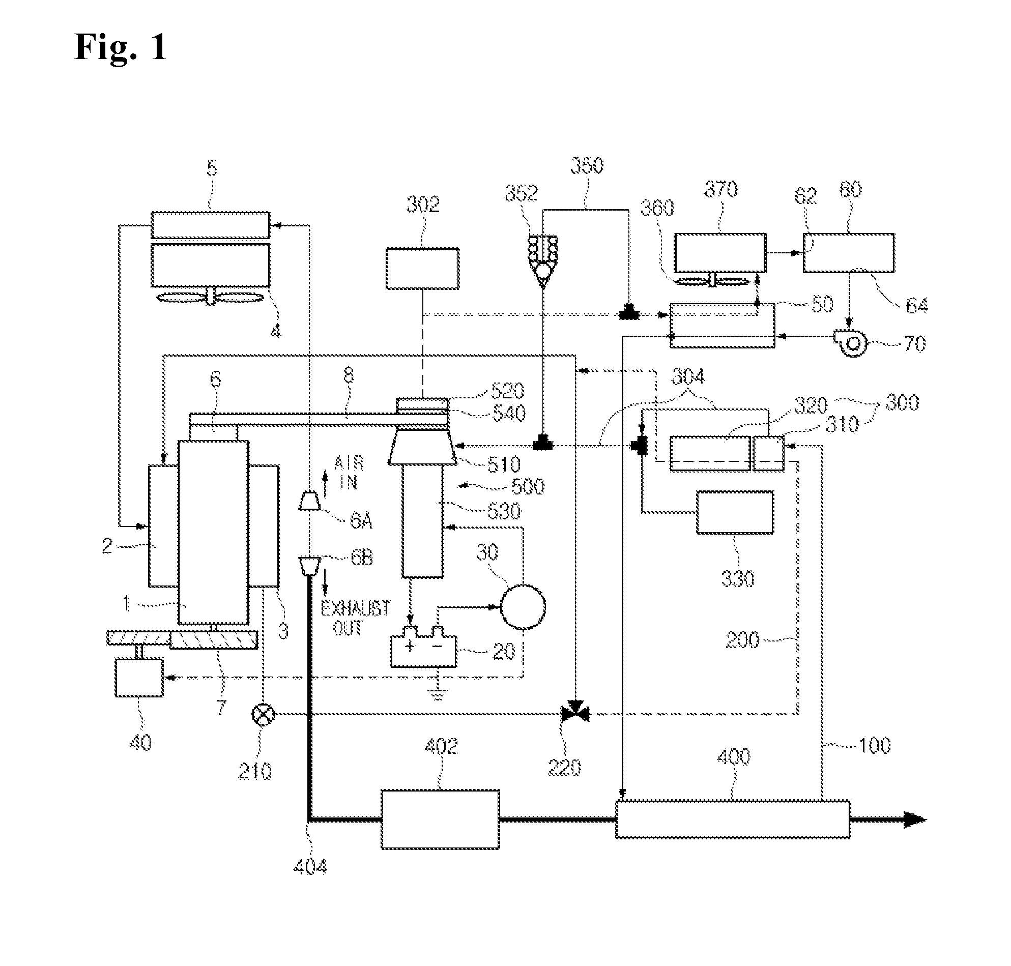
System of recycling exhaust heat from internal combustion engine

Active Publication Date: 2015-07-02
HYUNDAI MOTOR CO LTD
View PDF12 Cites 6 Cited by
  • Summary
  • Abstract
  • Description
  • Claims
  • Application Information

AI Technical Summary

Benefits of technology

The present invention aims to address the problems in the prior art while maintaining its advantages.

Problems solved by technology

The system using the turbo-compound is a scheme by attaching an exhaust turbine to an exhaust line and rotating the exhaust turbine by exhaust pressure to obtain an output, wherein this scheme may increase thermal efficiency of the entire system having the internal combustion engine installed therein, but may decrease the output of the engine itself due to the exhaust turbine acting as an exhaust resistance.
However, since cost of the thermoelectric element itself is negligible and a space in which the thermoelectric element may be mounted is narrow, it is difficult to significantly increase thermal efficiency of the engine even though the thermoelectric element is actually mounted in a mass-produced vehicle.
However, in the case in which the working fluid is circulated even when a temperature of the engine is low, it was found that fuel efficiency of the vehicle having the engine mounted therein is deteriorated.

Method used


Image

  • System of recycling exhaust heat from internal combustion engine
  • System of recycling exhaust heat from internal combustion engine

Examples


Embodiment Construction

[0026]Reference will now be made in detail to various embodiments of the present invention(s), examples of which are illustrated in the accompanying drawings and described below. While the invention(s) will be described in conjunction with exemplary embodiments, it will be understood that present description is not intended to limit the invention(s) to those exemplary embodiments. On the contrary, the invention(s) is / are intended to cover not only the exemplary embodiments, but also various alternatives, modifications, equivalents and other embodiments, which may be included within the spirit and scope of the invention as defined by the appended claims.

[0027]Terms and words used in the present specification and claims are not to be construed as a general or dictionary meaning but are to be construed as meaning and concepts meeting the technical ideas of the present invention based on a principle that the inventors can appropriately define the concepts of terms in order to describe t...


PUM


Abstract

A system of recycling exhaust heat from an internal combustion engine may include an EGR line circulating a portion of exhaust gas generated from the engine to an intake side, a working fluid circulating line configured to have a working fluid satisfying a Rankine cycle, which is circulated therein, and an EGR side heat exchanging unit configured to perform a heat-exchange between an EGR gas flowing in the EGR line and the working fluid flowing in the working fluid circulating line. When a temperature of the EGR gas is equal to or greater than a reference temperature T1, the EGR gas is circulated to the intake side via the EGR side heat exchanging unit, and when the temperature of the EGR gas is less than the reference temperature T1, the EGR gas is circulated to the intake side without passing through the EGR side heat exchanging unit.

Description

CROSS-REFERENCE TO RELATED APPLICATION[0001]The present application claims priority of Korean Patent Application Number 10-2013-0165243 filed on Dec. 27, 2013, the entire contents of which application are incorporated herein for all purposes by this reference.BACKGROUND OF INVENTION[0002]1. Field of Invention[0003]The present invention relates to a system of recycling exhaust heat from an internal combustion engine, and more particularly, to a system of recycling exhaust heat from an internal combustion engine including a recycling scheme circulating a working fluid using exhaust heat from the internal combustion engine.[0004]2. Description of Related Art[0005]An internal combustion engine is widely used in a vehicle, a ship, a small generator, and the like, and an attempt to increase efficiency of the internal combustion engine has been continuously conducted. The internal combustion engine generally discharges much heat as exhaust heat, and several systems collecting the exhaust h...

Claims


Application Information

Patent Timeline
IPC IPC(8): F01K23/06F01K23/14F01K7/16F02M25/07F01K23/10F01N5/02
CPCF01K23/065F01K23/10F01K23/14F01K7/16F02M25/0727F01N5/02F02G5/04F02G2260/00F01K5/02F02M26/25Y02T10/12F02G5/02
Inventor SON, YOU SANGHEO, KYOUNG
Owner HYUNDAI MOTOR CO LTD
Why Eureka
Try Eureka