Control device and control method for internal combustion engine
- Summary
- Abstract
- Description
- Claims
- Application Information
AI Technical Summary
Benefits of technology
Problems solved by technology
Method used
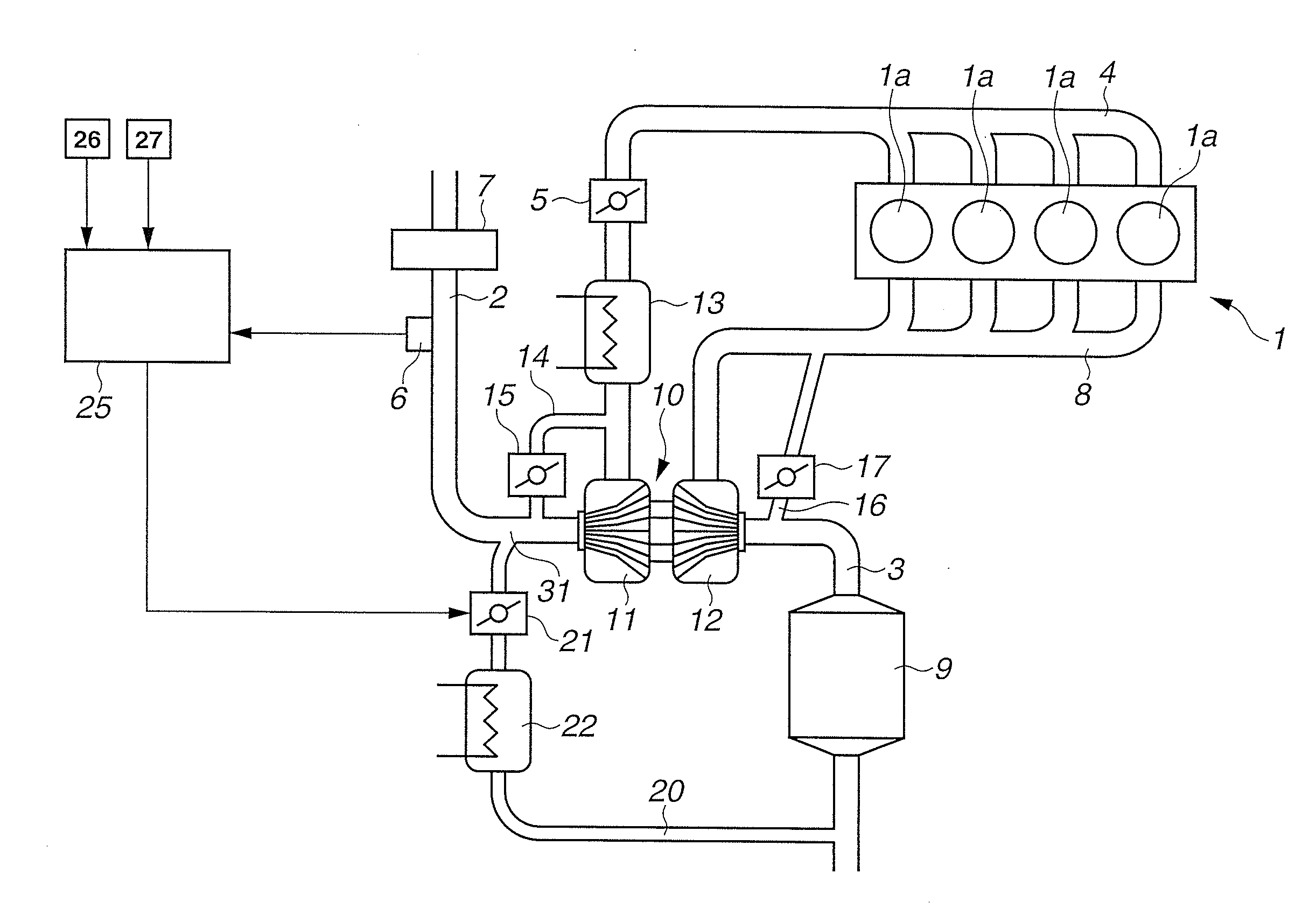
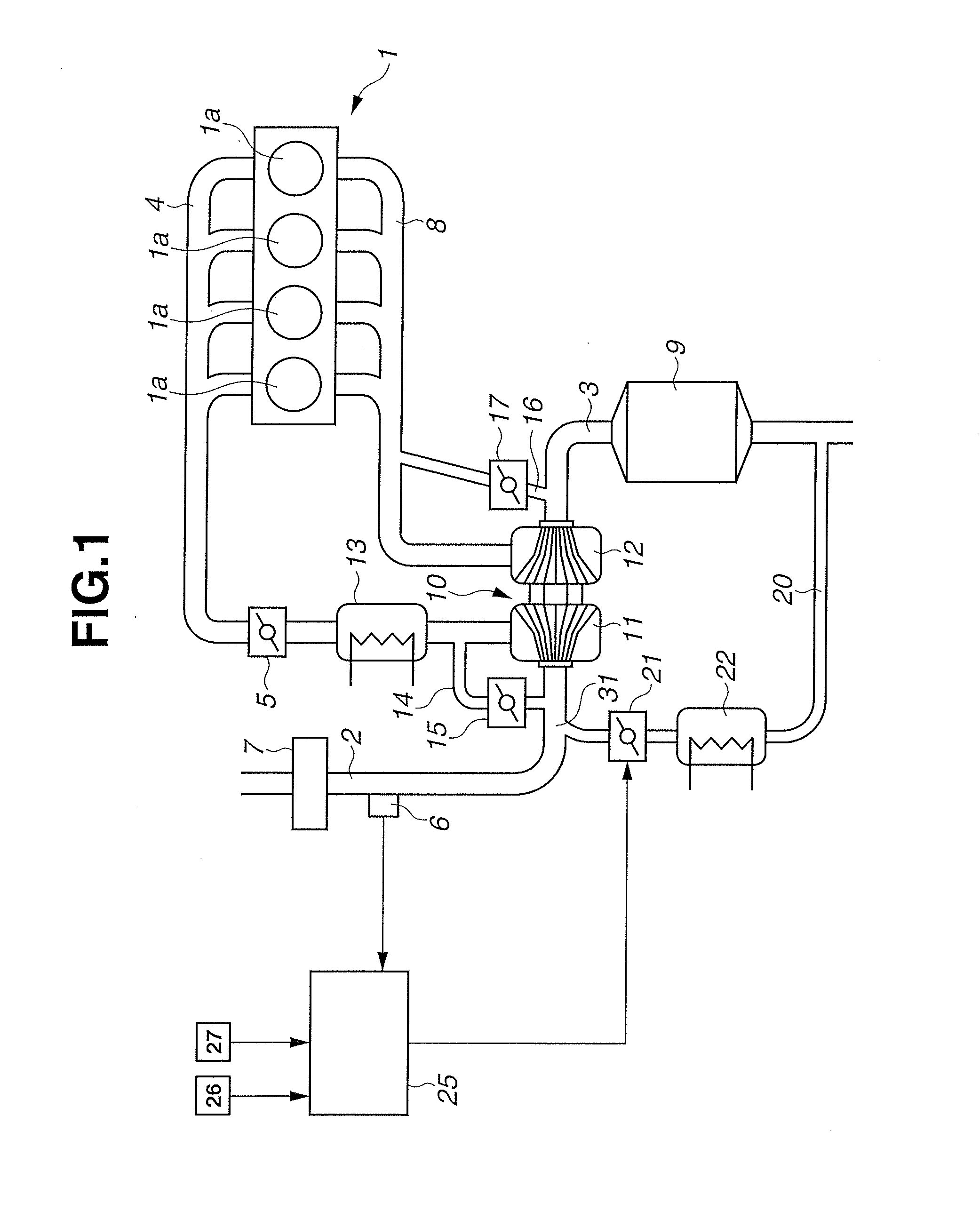
Image

Examples
first embodiment
[0046]FIG. 4 is a block diagram showing a control operation of the throttle valve 5 or the waste gate valve 17 in the first embodiment described above.
[0047]At S1, the EGR ratio in the first predetermined position is calculated using the target EGR ratio fixed by the operating condition, the quantity of the intake air and the volume of the flow passage from the EGR control valve 21 to the first predetermined position. That is, at S1, the EGR ratio in the first predetermined position in the case where the intake control device is the waste gate valve 17 is calculated. At S2, the quantity of the fresh air to be introduced into the cylinder is calculated using the EGR ratio calculated at S1.
[0048]At S3, the EGR ratio in the second predetermined position is calculated using the target EGR ratio fixed by the operating condition, the quantity of the intake air and the volume of the flow passage from the EGR control valve 21 to the second predetermined position. That is, at S3, the EGR rat...
second embodiment
[0060]FIG. 7 is a block diagram showing a control operation of the throttle valve 5 or the waste gate valve 17 in the second embodiment described above.
[0061]At S11, the first delay time from the time point at which the EGR control valve 21 is driven up to the time point at which the EGR ratio in the first predetermined position changes is calculated using the quantity of the intake air and the volume of the flow passage from the EGR control valve 21 to the first predetermined position.
[0062]At S12, the second delay time from the time point at which the EGR control valve 21 is driven up to the time point at which the EGR ratio in the second predetermined position changes is calculated using the quantity of the intake air and the volume of the flow passage from the EGR control valve 21 to the second predetermined position. At S13, the intake control device is selected.
[0063]At S14, the target intake air quantity is calculated according to the engine demand torque and the opening degr...
PUM
 Abstract
Description
Claims
Application Information
 - Generate Ideas
- Intellectual Property
- Life Sciences
- Materials
- Tech Scout
- Unparalleled Data Quality
- Higher Quality Content
- 60% Fewer Hallucinations
Browse by: Latest US Patents, China's latest patents, Technical Efficacy Thesaurus, Application Domain, Technology Topic, Popular Technical Reports.
© 2025 PatSnap. All rights reserved.Legal|Privacy policy|Modern Slavery Act Transparency Statement|Sitemap|About US| Contact US: help@patsnap.com