Laser light source

a laser light source and laser technology, applied in the field of laser light sources, can solve the problems of difficult to focus the multicolor light at one point, and achieve the effect of reducing the wavelength-dependent difference of the position (beam waist) and reducing the wavelength-dependent focal position differen

Inactive Publication Date: 2015-07-02
SUMITOMO ELECTRIC IND LTD
View PDF0 Cites 26 Cited by
  • Summary
  • Abstract
  • Description
  • Claims
  • Application Information

AI Technical Summary

Benefits of technology

[0013]The present embodiment provides the laser light source incorporating the collimator device which, when collimating the multicolor light with the wide spectral width, is capable of more reducing the wavelength-dependent difference o...

Problems solved by technology

Due to it, a position (beam waist) where the light emitted from the end face of the optical fiber becomes a plane wave after collimated, with respect to the end...

Method used


Image

  • Laser light source
  • Laser light source
  • Laser light source

Examples


Embodiment Construction

[0028]Each embodiment of the present invention will be described below in detail with reference to the accompanying drawings. In the description of the drawings the same portions and the same elements will be denoted by the same reference signs, without redundant description.

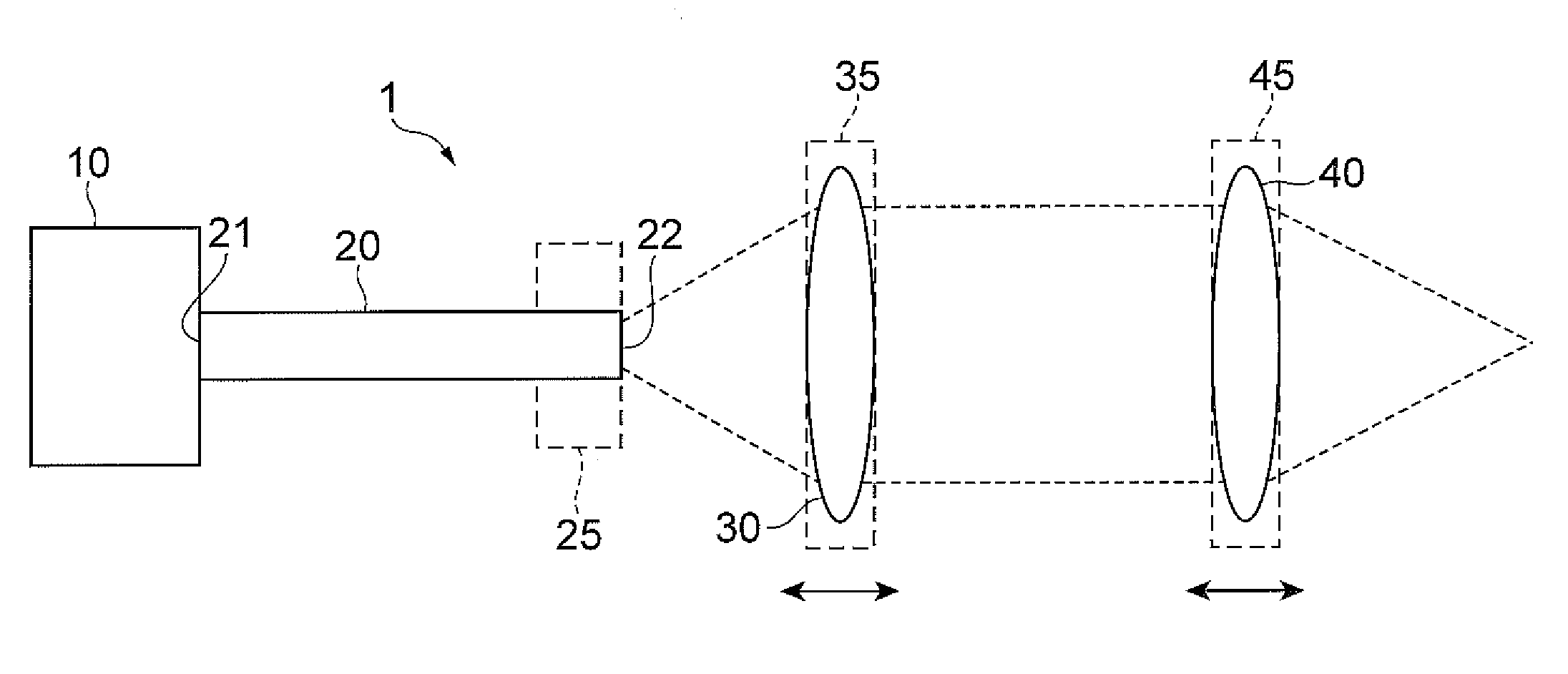
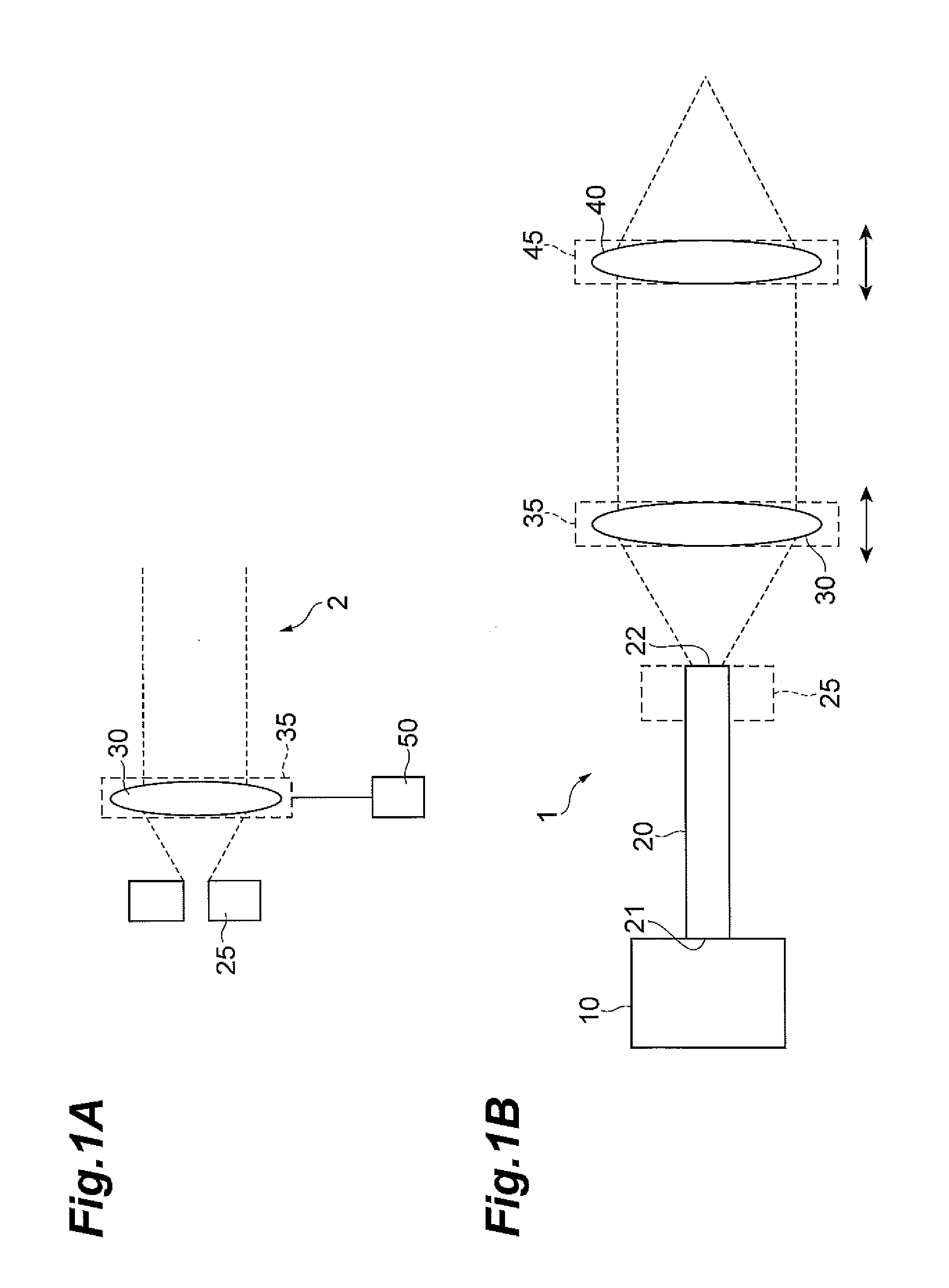
[0029]FIGS. 1A and 1B are schematic configuration diagrams of a collimator device 2 and a laser light source 1 of the first embodiment incorporating it. The collimator device 2 in FIG. 1A is composed of a laser light entrance portion 25 which sets an exit position of laser light, a collimating lens 30, a collimating lens installation portion 35 which fixes the collimating lens 30, and a position adjustment portion 50 which adjusts the position of the laser light entrance portion, in order to adjust the distance between the laser light exit position (optical fiber exit end face) 22 of the laser light entrance portion 25 and the position of the collimating lens 30. The position adjustment portion 50 may be install...


PUM

PropertyMeasurementUnit
Lengthaaaaaaaaaa
Lengthaaaaaaaaaa
Nanoscale particle sizeaaaaaaaaaa

Abstract

The present invention relates to a laser light source which reduces wavelength-dependent difference of focal position of condensed light when multicolor light with a wide spectral width is collimated and then condensed. The laser light source incorporates a collimator device, in which an installation position of a collimating lens with respect to a laser light entrance portion is set so that a beam waist position of laser light having passed through the collimating lens shifts closer to the collimating lens with a shorter-wavelength-side wavelength component out of wavelength components included in the laser light.

Description

TECHNICAL FIELD[0001]The present invention relates to a laser light source incorporating a collimator device for collimating input light with a wide spectral width, and configured to collimate and then condense the input light with the wide spectral width, thereby realizing laser irradiation.BACKGROUND ART[0002]Processing using laser light is carried out by use of a configuration wherein laser light divergently emitted from an end face of an optical fiber is collimated and thereafter the collimated laser light is condensed by using a condensing lens, to focus the laser light at a point on a workpiece. When the laser light is multicolor light with a wide spectral width such as white light, the focal length differs depending upon the wavelengths of the light. Due to it, a position (beam waist) where the light emitted from the end face of the optical fiber becomes a plane wave after collimated, with respect to the end face of the optical fiber also differs depending upon the wavelength...

Claims


Application Information

Patent Timeline
IPC IPC(8): G02B27/30G02B27/00G02B19/00H01S3/00H01S3/067
CPCG02B27/30H01S3/005G02B27/0025G02B19/0014G02B19/0047H01S3/067B23K26/0648B23K26/0665
Inventor NAGANO, SHIGEHIRO
Owner SUMITOMO ELECTRIC IND LTD
Why Eureka
Try Eureka