
Method and system for predicting block failure in a non-volatile memory

a non-volatile memory and block failure technology, applied in the direction of memory adressing/allocation/relocation, instruments, input/output to record carriers, etc., can solve the problems of flash storage systems generally failing, storage systems that fail, waste of blocks with more remaining life, etc., to improve the overall life of storage devices, reduce wear burden, and increase wear burden

Active Publication Date: 2015-07-02
SANDISK TECH LLC
View PDF3 Cites 76 Cited by
  • Summary
  • Abstract
  • Description
  • Claims
  • Application Information

AI Technical Summary

Benefits of technology

The patent describes a storage device with a controller that can predict when a memory block will reach the end of its lifespan and wear down other blocks. This helps to shift more wear burden to blocks that are predicted to have a longer lifespan and reduce wear on blocks that are predicted to have a shorter lifespan. Overall, this improves the overall life of the storage device by reducing wear and tear on certain parts.

Problems solved by technology

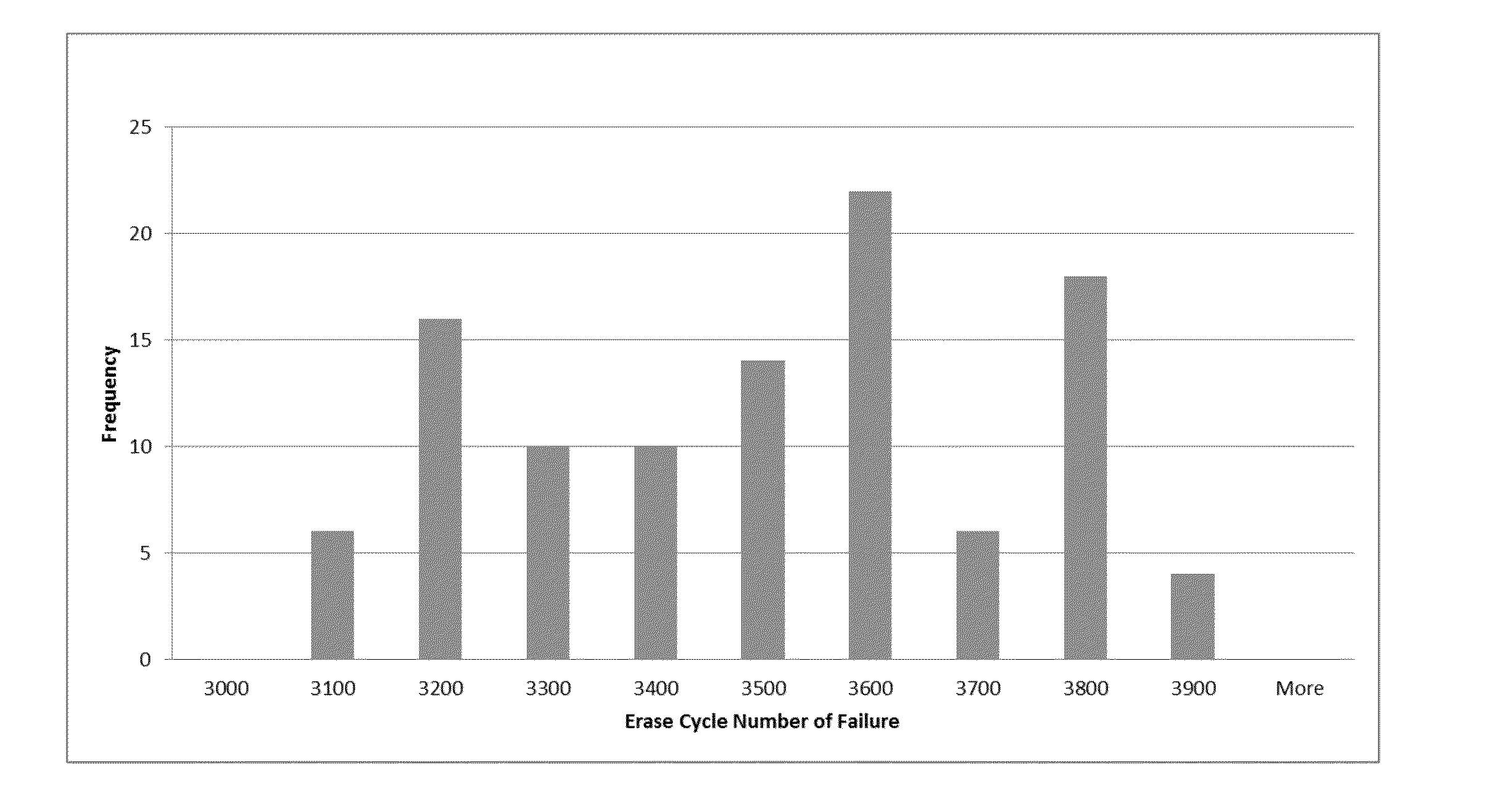
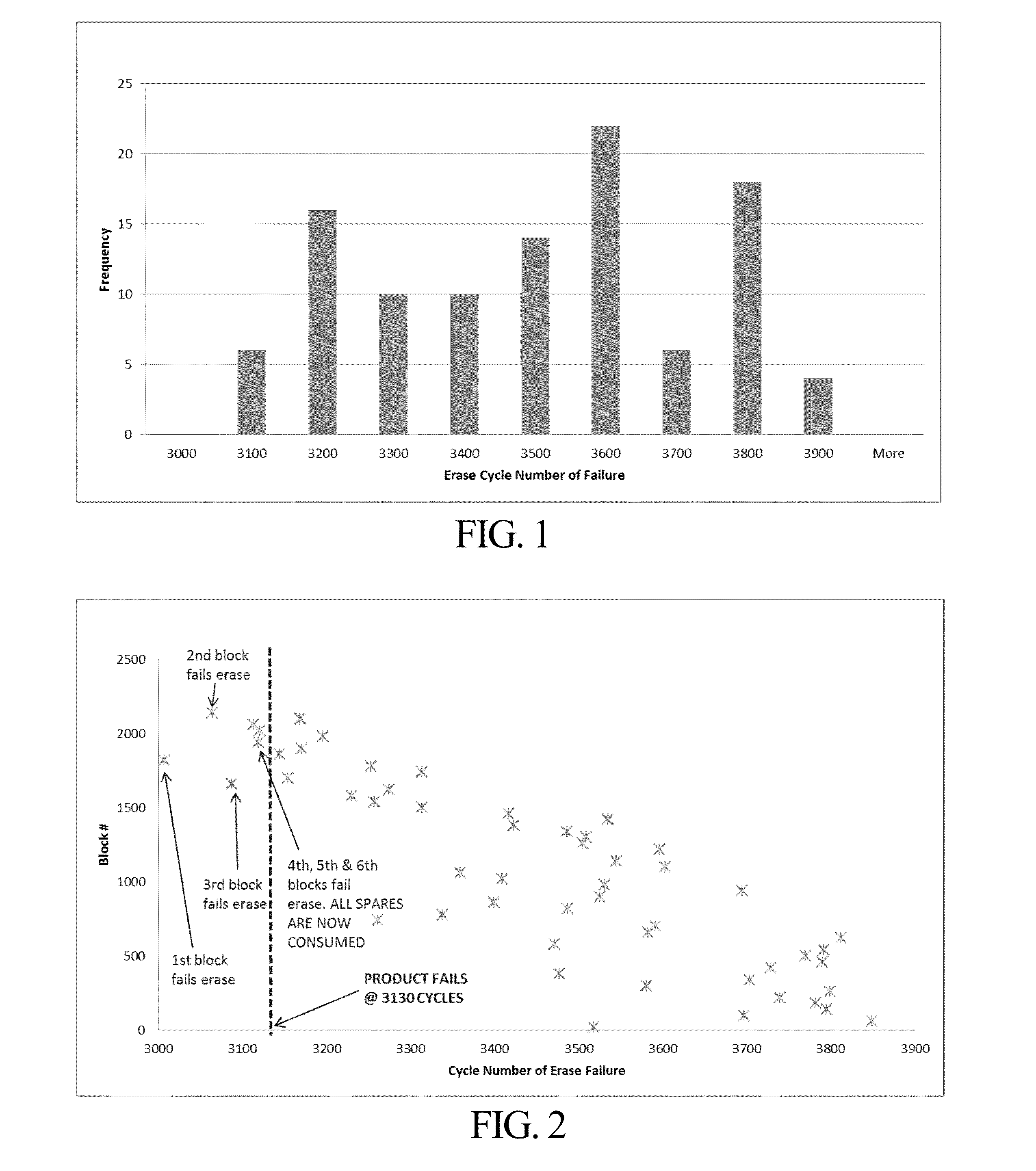
Flash storage systems generally fail when they run out of spare blocks to replace blocks that have been retired because they failed to erase.
Although this may avoid problems with concentrating program / erase cycles on only a few blocks, it is based on the assumption that blocks have the same lifespan (in terms of having the same number of program / erase cycles before failure) and may result in a storage system that fails based on the weakest blocks and wastes blocks with more remaining life for a storage system that has a failure distribution such as shown in FIG. 1
A typical low-cost flash storage system may only have a few spare blocks available and, once the number of spares available has been consumed due to eventual failure of some of the blocks, the storage system itself can no longer accept data (i.e., fails) and becomes a read-only device.
However, this erase cycle life in the remaining good blocks is wasted because of the worst few blocks that failed first in this hot-count based wear leveling system.

Method used


Image

  • Method and system for predicting block failure in a non-volatile memory
  • Method and system for predicting block failure in a non-volatile memory
  • Method and system for predicting block failure in a non-volatile memory

Examples


Embodiment Construction

[0028]A method and system for predicting which blocks in a non-volatile memory are going to fail first, and application of that knowledge to improved management of those memory blocks, are disclosed herein. In one embodiment, a metric on which the prediction of block erase cycle life is based is the erase cycle count at which point a block first exceeds a threshold amount of time to successfully erase. One or more threshold erase times may be tracked for each block as described in greater detail below.

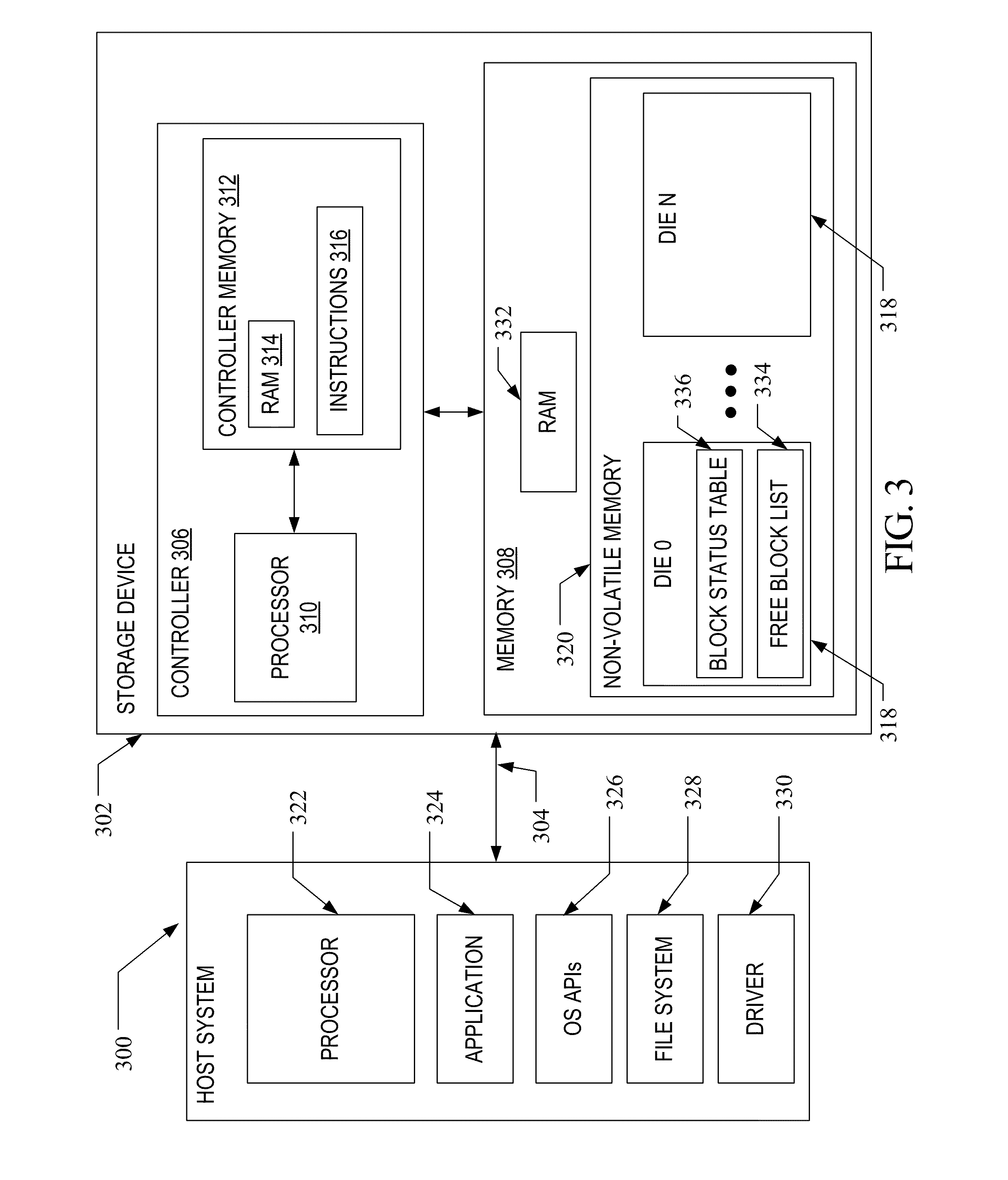
[0029]A non-volatile memory system suitable for use in implementing aspects of the invention is shown in FIG. 3. A host system 300 stores data into, and retrieves data from, a storage device 302. The storage device 302 may be embedded in the host system 300 or may exist in the form of a card or other removable drive, such as a solid state disk (SSD) that is removably connected to the host system 300 through a mechanical and electrical connector. The host system 300 may be any of a numb...


PUM


Abstract

A method and system are disclosed for improved block erase cycle life prediction and block management in a non-volatile memory. The method includes the storage device tracking information relating to a first erase cycle count at which the block erase time exceeded a predetermined threshold relative to a first erase cycle at which this occurred in other blocks. Blocks having a later relative erase cycle at which the erase time threshold is exceeded are assumed to have a greater erase cycle life than those that need to exceed the erase time threshold at an earlier erase cycle. This information is used to adjust wear leveling in the form of free block selection, garbage collection block selection and other block management processes. Alternatively or in combination, the predicted erase cycle life information is used to adjust program and / or erase parameters such as erase voltage and time.

Description

TECHNICAL FIELD[0001]This application relates generally to a method and system for predicting relative memory block life in a non-volatile memory.BACKGROUND[0002]Non-volatile memory systems, such as flash memory, are used in digital computing systems as a means to store data and have been widely adopted for use in consumer products. Flash memory may be found in different forms, for example in the form of a portable memory card that can be carried between host devices or as a solid state disk (SSD) embedded in a host device. These memory systems typically work with data units called “pages” that can be written, and groups of pages called “blocks” that can be read and erased, by a storage manager often residing in the memory system.[0003]Flash storage systems generally fail when they run out of spare blocks to replace blocks that have been retired because they failed to erase. Blocks in a typical storage system tend not to fail at the same time. Rather, blocks often fail at different ...

Claims


Application Information

Patent Timeline
Patent Type & Authority Applications(United States)
IPC IPC(8): G06F3/06G11C29/44G06F12/02G11C29/12G11C16/34G11C29/10G11C29/38
CPCG06F3/0616G11C29/10G11C29/44G11C29/38G06F12/0246G11C16/3445G06F3/0653G06F3/0679G11C29/12015G06F2212/7211G11C16/16G11C16/349G11C29/028G11C29/50004G11C2029/0409
Inventor DARRAGH, NEIL RICHARD
Owner SANDISK TECH LLC
Learn More