
Engine fuel control system

a fuel control system and engine technology, applied in the direction of engine starters, engines/propulsion engines, turbine/propulsion engine ignition, etc., can solve the problems of limited use of actuators and servo-valve components, increased risk of damage to pump bearings, etc., to improve the thermal efficiency of the system, reduce the load on the main pump, and achieve the effect of adequate fuel pressure for the operation of auxiliary engine devices

Active Publication Date: 2015-07-09
ROLLS ROYCE PLC
View PDF6 Cites 18 Cited by
  • Summary
  • Abstract
  • Description
  • Claims
  • Application Information

AI Technical Summary

Benefits of technology

This patent describes a system for supplying fuel to an auxiliary engine device in an aircraft. The system includes a main pump and an augmenter pump. The main pump provides fuel to the engine at low speeds, while the augmenter pump provides additional fuel to the engine at high speeds. This setup helps ensure that the engine has enough fuel flow and pressure to operate all its devices. The system also includes a pressure drop control valve that adjusts the flow rate of the augmenter pump based on the difference between high and low pressures. This allows for a constant maximum flow rate, even at high engine speeds. Overall, the system allows for efficient fuel delivery to the engine at both low and high speeds.

Problems solved by technology

However, the use of larger actuators and servo-valves may be limited by space constraints.
In addition, raising the minimum pump pressure rise (HP-LP) increases heat input to the fuel and increases the risk of damage to the pump bearings, which have to run on thinner bearing film thicknesses at high pressure, low speed conditions.

Method used


Image

  • Engine fuel control system
  • Engine fuel control system
  • Engine fuel control system

Examples


Embodiment Construction

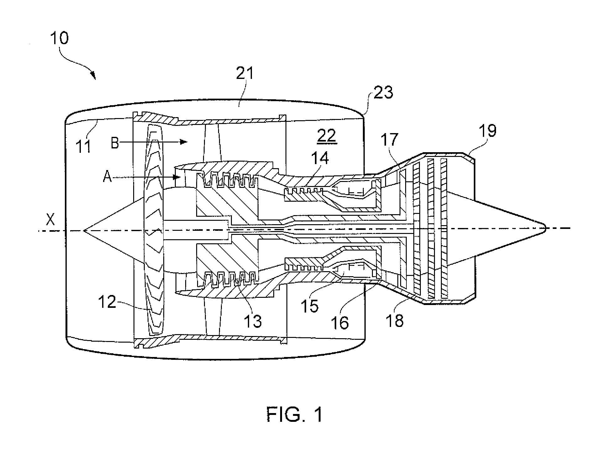
[0032]With reference to FIG. 1, a ducted fan gas turbine engine incorporating the invention is generally indicated at 10 and has a principal and rotational axis X-X. The engine comprises, in axial flow series, an air intake 11, a propulsive fan 12, an intermediate pressure compressor 13, a high-pressure compressor 14, combustion equipment 15, a high-pressure turbine 16, an intermediate pressure turbine 17, a low-pressure turbine 18 and a core engine exhaust nozzle 19. A nacelle 21 generally surrounds the engine 10 and defines the intake 11, a bypass duct 22 and a bypass exhaust nozzle 23.

[0033]During operation, air entering the intake 11 is accelerated by the fan 12 to produce two air flows: a first air flow A into the intermediate pressure compressor 13 and a second air flow B which passes through the bypass duct 22 to provide propulsive thrust. The intermediate pressure compressor 13 compresses the air flow A directed into it before delivering that air to the high pressure compres...


PUM


Abstract

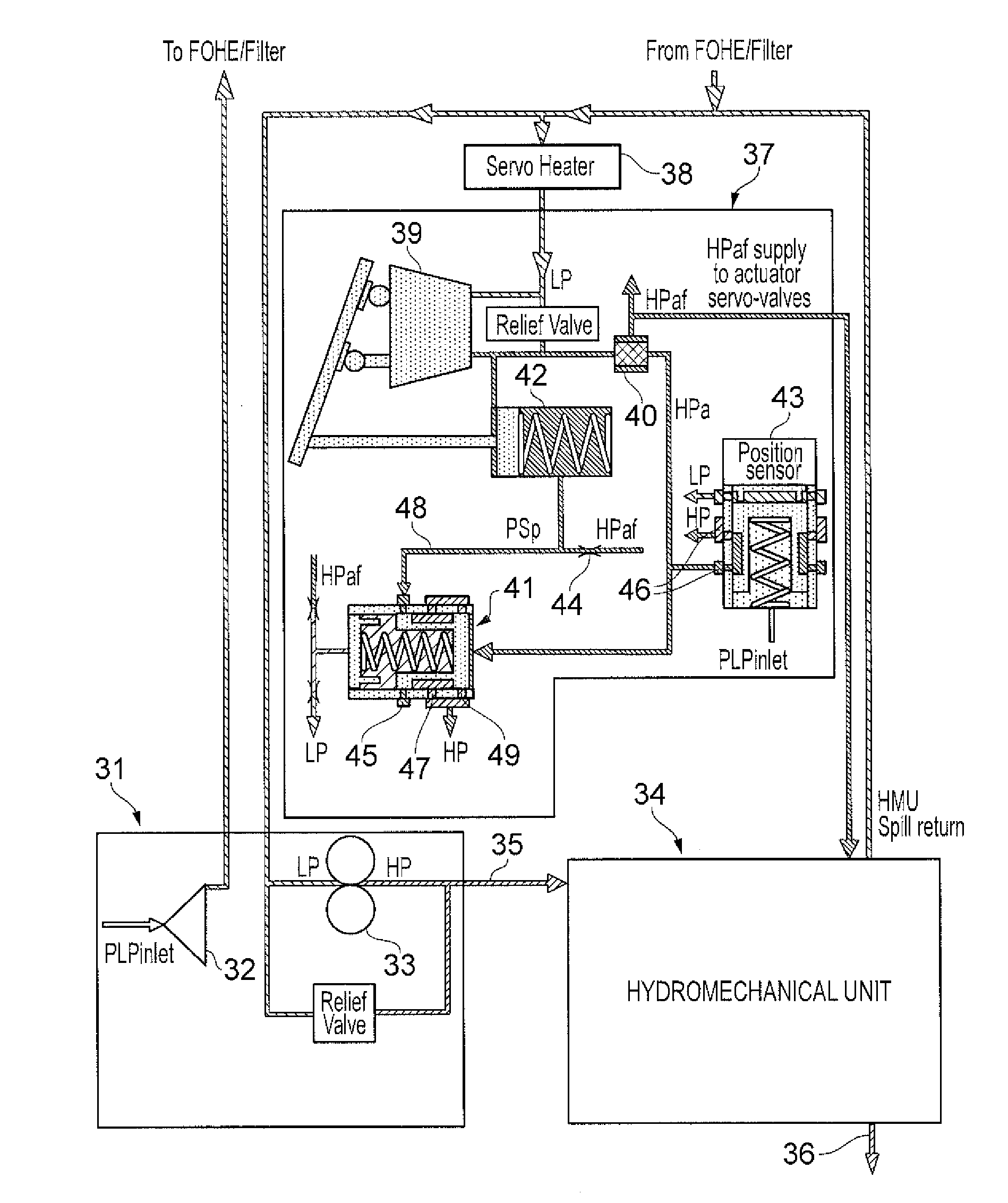
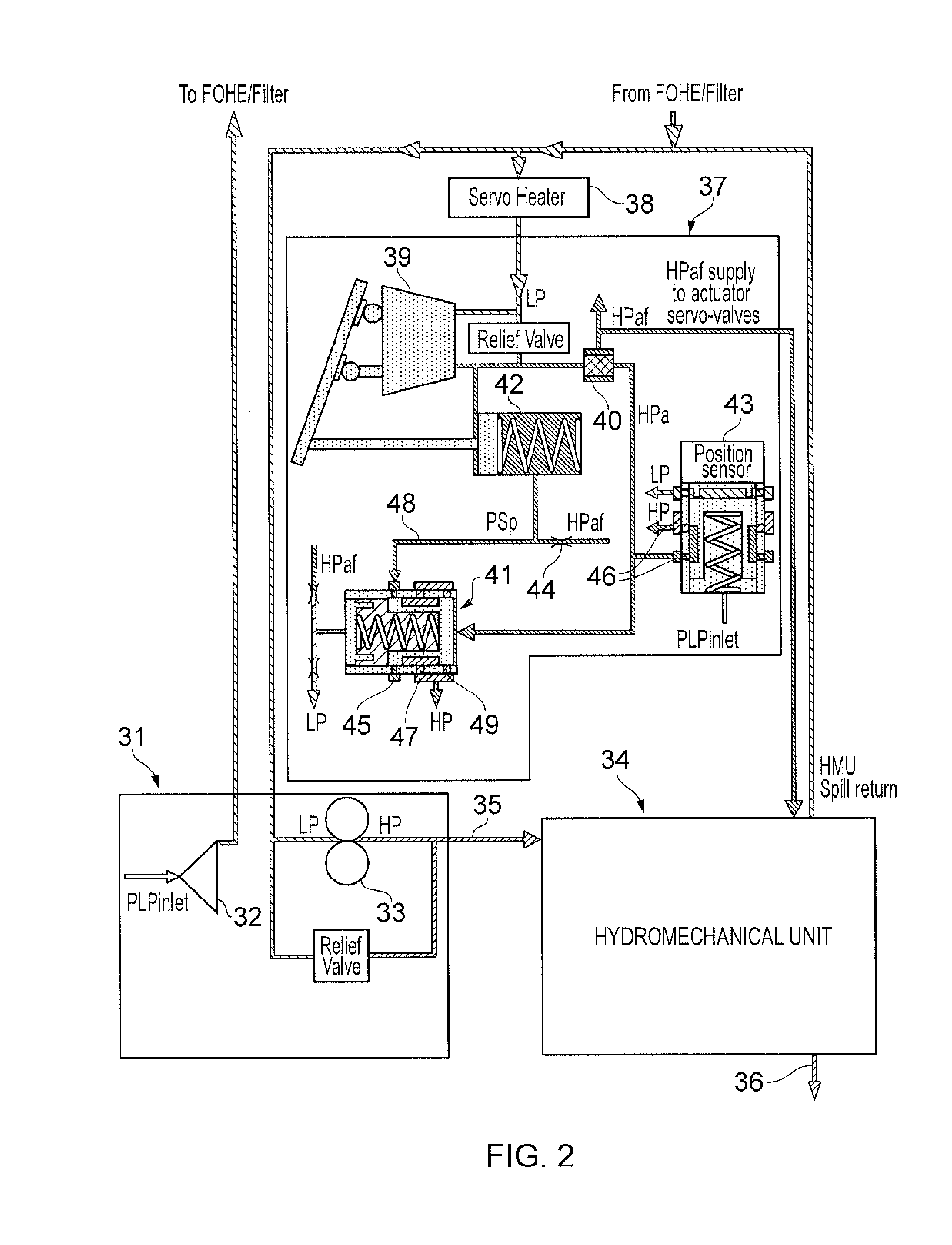
An engine fuel control system includes a fuel metering valve that controls the flow of fuel between supply and delivery lines which delivers fuel to engine burners. The fuel control system includes a fixed displacement main pump which receives fuel from a low pressure source and delivers the fuel at a first high pressure to the supply line, an augmenter pump which receives fuel from the low pressure source and delivers the fuel at a second high pressure to one or more fuel-pressure operated auxiliary engine devices, and a start valve which is actuated at low engine speeds to open a flow path which diverts fuel delivered by the augmenter pump away from the auxiliary engine devices to the supply line to augment the fuel delivered thereto by the main pump, the start valve being actuated at higher engine speeds to shut the flow path.

Description

FIELD OF THE INVENTION[0001]The present invention relates to an engine fuel control system and in particular to a fuel control system for use in controlling the supply of fuel to a gas turbine engine.BACKGROUND OF THE INVENTION[0002]Fuel control systems, of the type described in U.S. Pat. No. 7,137,242, are used in controlling the supply of fuel to an aircraft engine. Such systems have a hydro-mechanical unit (HMU) which contains a metering valve and which receives a supply of fuel at high pressure (HP) from a gear pump driven from, and thus operated at a speed related to, the main shaft of the associated gas turbine engine. The inlet of the gear pump is supplied from a fuel reservoir by means of a boost pump or lift pump, the pressure at the inlet of the gear pump being defined as low pressure (LP), which in practice may be above atmospheric pressure but substantially below HP. The supply line from the outlet of the gear pump contains a fuel filter and enters the HMU to provide an ...

Claims


Application Information

Patent Timeline
Patent Type & Authority Applications(United States)
IPC IPC(8): F02C9/30F02C9/28
CPCF02C9/30F02C9/28F05D2220/323F05D2270/07F05D2270/66F05D2270/03F01D19/00F02C7/236F02C7/26F05D2260/85F05D2270/304F05D2270/56F05D2270/64Y02T50/60F02C9/32
Inventor GRIFFITHS, MICHAEL
Owner ROLLS ROYCE PLC
Learn More