Pipeline fastener

Inactive Publication Date: 2015-07-09
HUMBOLDT STATE UNIVERSITY
View PDF6 Cites 4 Cited by
  • Summary
  • Abstract
  • Description
  • Claims
  • Application Information

AI Technical Summary

Benefits of technology

[0007]The purpose of the present invention is to provide a pipeline fastener which certainly prevents t

Problems solved by technology

If the burrs 2 fall and flow with the fluid in time of use, the pipes a,b or pumps are most probably damaged.
Consequently, the conventional operation has a poor burr-removal effect.

Method used


Image

  • Pipeline fastener
  • Pipeline fastener
  • Pipeline fastener

Examples


Embodiment Construction

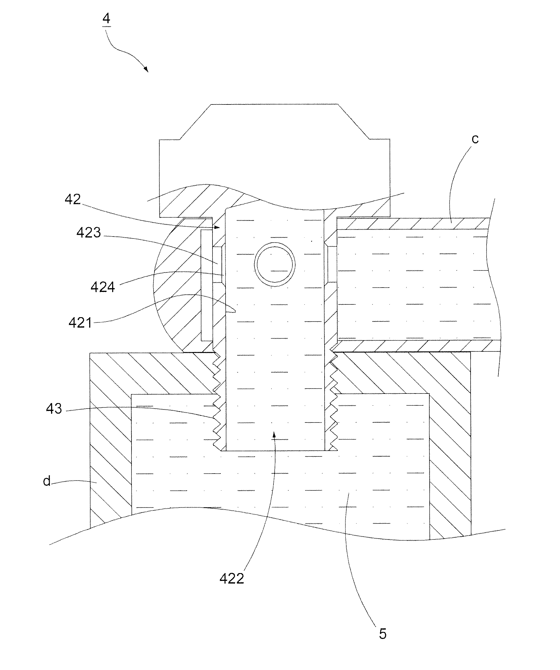
[0020]Accompanying with FIG. 4 and FIG. 5, a first preferred embodiment of the pipeline fastener 4 is shown. The pipeline fastener 4 comprises a screw head 41, a hollow shank 42 outwardly extended from the screw head 41, and a plurality of threaded units 43 spirally disposed on the shank 42. Wherein, the shank 42 contains an outer wall 425 in contact with an outside, a channel 422 being enclosed by an inner wall 421 defined inside the shank 42. One end of the channel 422 opposite to the screw head 41 is communicated with the outside. As a result, that end inside the shank 42 is formed into an open state, and the other end thereof is blocked by the screw head 41. At least one hole 423 enclosed by a bore surface 4231 is formed on the shank 42, the bore surface 4231 is connected to a chip-removing surface 4232 which is jointed to the inner wall 421, and a chip-removing section 424 is enclosed by the chip-removing surface 4232. Whereby, the chip-removing section 424 is formed between th...


PUM


Abstract

A pipeline fastener defines at least one hole formed on a hollow shank with a channel formed therein and has a chip-removing section at least formed between the hole and the channel of the shank. A diameter of the chip-removing section is bigger than a bore diameter of the hole. Accordingly, by the chip-removing section with the bigger diameter, burrs which are originally formed at a convergence between a bore surface of the hole and a periphery of the shank can be removed. Consequently, following burr-cleaning procedures are reduced to lower the production cost, and damages of the burrs to other objects at the time of using the pipeline fastener are further prevented, thereby improving the safety of the use efficiently.

Description

BACKGROUND OF THE INVENTION[0001]1. Field of the Invention[0002]The present invention pertains to a fastener, in particular to a pipeline fastener.[0003]2. Description of the Related Art[0004]An ordinary pipeline fastener is usually applied to fasten and connect two pipes. By means of the pipeline fastener, the two pipes can be communicated with each other, whereby the pipeline fastener is usually used in a hydraulic brake system of vehicles, such as a joint for connecting a brake fluid container with a brake fluid pipe. Consequently, the pipeline fastener is widely applied to varied fields.[0005]Referring to FIG. 1 and FIG. 2, a conventional pipeline fastener 1 comprises a head 11, a shank 12 connected to the head 11, and a plurality of threads 13 spirally disposed on the shank 12. Wherein, a channel 122 is enclosed by an inner wall 121 defined inside the shank 12. One end of the channel 122 opposite to the head 11 is communicated with an outside. At least one hole 123 penetrating ...

Claims


Application Information

Patent Timeline
IPC IPC(8): F16B35/04
CPCF16B35/04B60T17/043
Inventor HSU, HUNG-I
Owner HUMBOLDT STATE UNIVERSITY
Why Eureka
Try Eureka