Multi-Cone Fuel Burner Apparatus For Multi-Tube Heat Exchanger

a fuel burner and multi-tube technology, applied in lighting and heating apparatus, combustion types, heating types, etc., can solve the problems of unsatisfactory high temperature inside the heating appliance cabinet, unsatisfactory operation noise, and unacceptably large operating nois

Inactive Publication Date: 2015-07-09
RHEEM MFG CO
View PDF24 Cites 20 Cited by
  • Summary
  • Abstract
  • Description
  • Claims
  • Application Information

AI Technical Summary

Problems solved by technology

A variety of well known problems, limitations and disadvantages are present in this conventional design of a premixed fuel / air combustion system and are primarily created by the use of the flat burner 32.
High temperatures inside the heating appliance cabinet is not desirable because it can cause problems for the other components and it also is a form of efficiency reducing heat loss.
Moreover, the flat burner 32 has been found to often be a primary source of an undesirable source of operating noise, including ignition noise, structural vibration noise and steady state high frequency noise.
Replacing the flat burner 32 with a curved single burner has been found to at least somewhat alleviate the bowing problem of the flat burner, but still can create an unacceptably large level of operational noise when used in a premixed fuel / air combustion application.

Method used


Image

  • Multi-Cone Fuel Burner Apparatus For Multi-Tube Heat Exchanger
  • Multi-Cone Fuel Burner Apparatus For Multi-Tube Heat Exchanger
  • Multi-Cone Fuel Burner Apparatus For Multi-Tube Heat Exchanger

Examples


Embodiment Construction

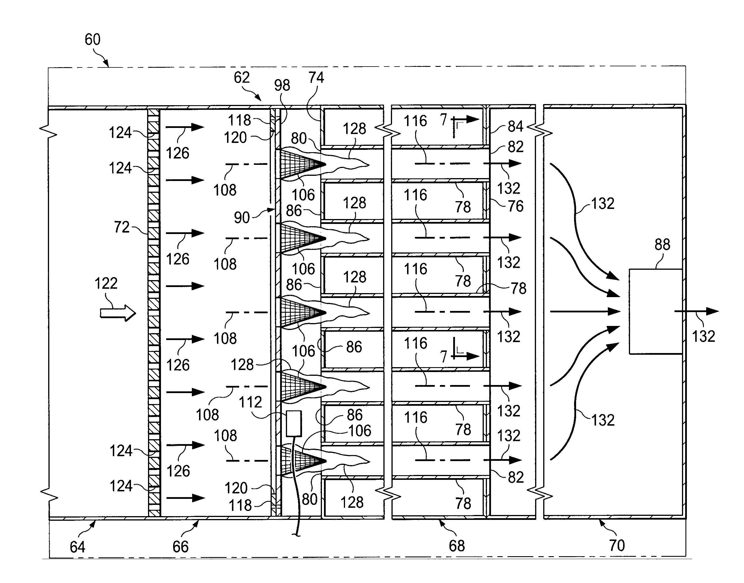
[0019]Cross-sectionally depicted in schematic form in FIG. 3 is a portion of a fuel-fired heating appliance, representatively an air heating furnace 60, that incorporates therein a premixed fuel / air combustion section 62 embodying principles of the present invention. While the heating appliance 60 is representatively an air heating furnace, principles of the present invention are not limited to furnaces, and could be employed to advantage in a variety of other types of fuel-fired heating appliances including, but not limited to, water heaters, boilers and pool heaters.

[0020]The combustion section 62 comprises, from left to right in FIG. 3, a mixing box 64, a burner box or combustion chamber 66, a heat exchange housing 68, and a collector box 70 joined together as indicated. At the juncture of the mixing box 64 and the burner box is a perforated diffuser plate 72 which may be similar in configuration and operation to the perforated diffuser plate 64 illustrated and described in copen...


PUM


Abstract

Installed in a fuel-fired heating appliance is a specially designed burner assembly operative to receive and combust a pre-mixed flow of fuel and air to create therefrom a spaced apart plurality of flames which are aligned with and flow directly into the inlets of a corresponding spaced plurality of heat exchanger tubes. The flames create within the tubes hot combustion gases that transfer combustion heat to a supply fluid flowed externally across the tubes. The burners are of a hollow perforate metal construction, are mounted on and forwardly project from a support structure toward the tube inlets, and have rearwardly facing open inlet ends that receive the pre-mixed flow of fuel and air. In one illustrated embodiment thereof, the burners have conical configurations, and in another illustrated embodiment have generally dome-shaped configurations. Via a flame carryover structure, a single igniter is utilized to ignite all of the burners.

Description

BACKGROUND OF THE INVENTION[0001]The present invention relates generally to fuel-fired heating appliances, such as air heating furnaces, and more particularly provides specially designed combustion apparatus for such fuel-fired heating appliances.[0002]In fuel-fired heating appliances such as, for example, air heating furnaces, a known firing method is to flow a fuel / air mixture into a burner box structure in which a burner structure and an associated igniter structure are disposed and are operative to combust the fuel / air mixture and thereby create hot combustion gases used to heat air (or another fluid as the case may be) for delivery to a location served by the heating appliance. The hot combustion gases are flowed through a series of heat exchanger tubes, externally across which the fluid to be heated is flowed, and then discharged from the heating appliance into a suitable flue structure.[0003]Typically, spaced apart open inlet portions of the heat exchanger tubes extend throug...

Claims


Application Information

Patent Timeline
Patent Type & Authority Applications(United States)
IPC IPC(8): F23D14/14F24H9/18F23D23/00F24H3/08F24D5/04F23D14/02
CPCF23D14/14F24D5/04F23D14/02F24H2210/00F24H3/087F24H9/1881F23D2203/103F23D23/00F23D2203/101F23D2900/00003
Inventor AKBARIMONFARED, AMINSHELLENBERGER, TIMOTHY J.FARLEY, DARRYL J.WHALEN, NATHAN T.THOMPSON, TRENT E.
Owner RHEEM MFG CO
Why Eureka
Try Eureka