Switched power stage and a method for controlling the latter

Active Publication Date: 2015-07-09
CHAOYANG SEMICON (SHANGHAI) CO LTD
View PDF4 Cites 15 Cited by
  • Summary
  • Abstract
  • Description
  • Claims
  • Application Information

AI Technical Summary

Benefits of technology

[0026]These and other aspects of the invention are mo

Problems solved by technology

When one or more circuits of the device are deactivated, the current drawn by the device may drop very shortly, thus resulting in a voltage overshoot if the supplied current does not follow this drop.
Such a big inductor cannot be compact and integrated in

Method used


Image

  • Switched power stage and a method for controlling the latter
  • Switched power stage and a method for controlling the latter
  • Switched power stage and a method for controlling the latter

Examples


Embodiment Construction

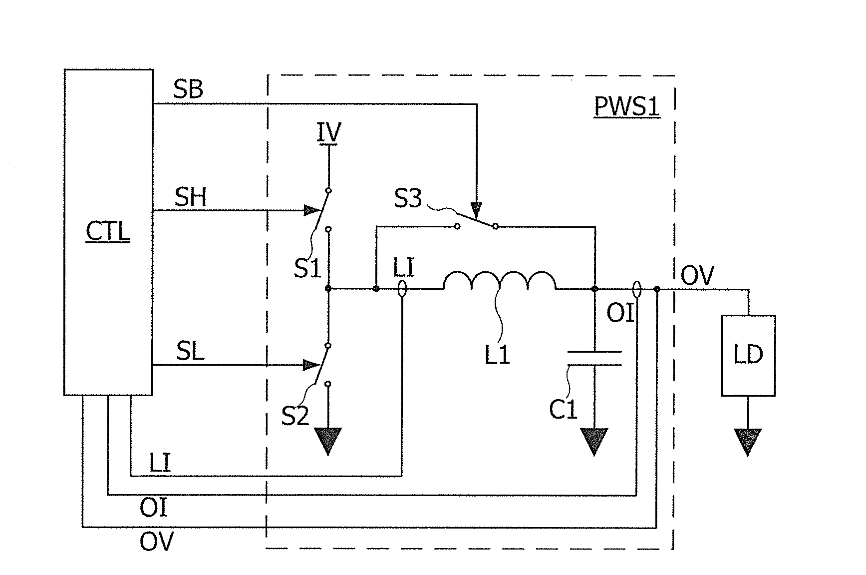
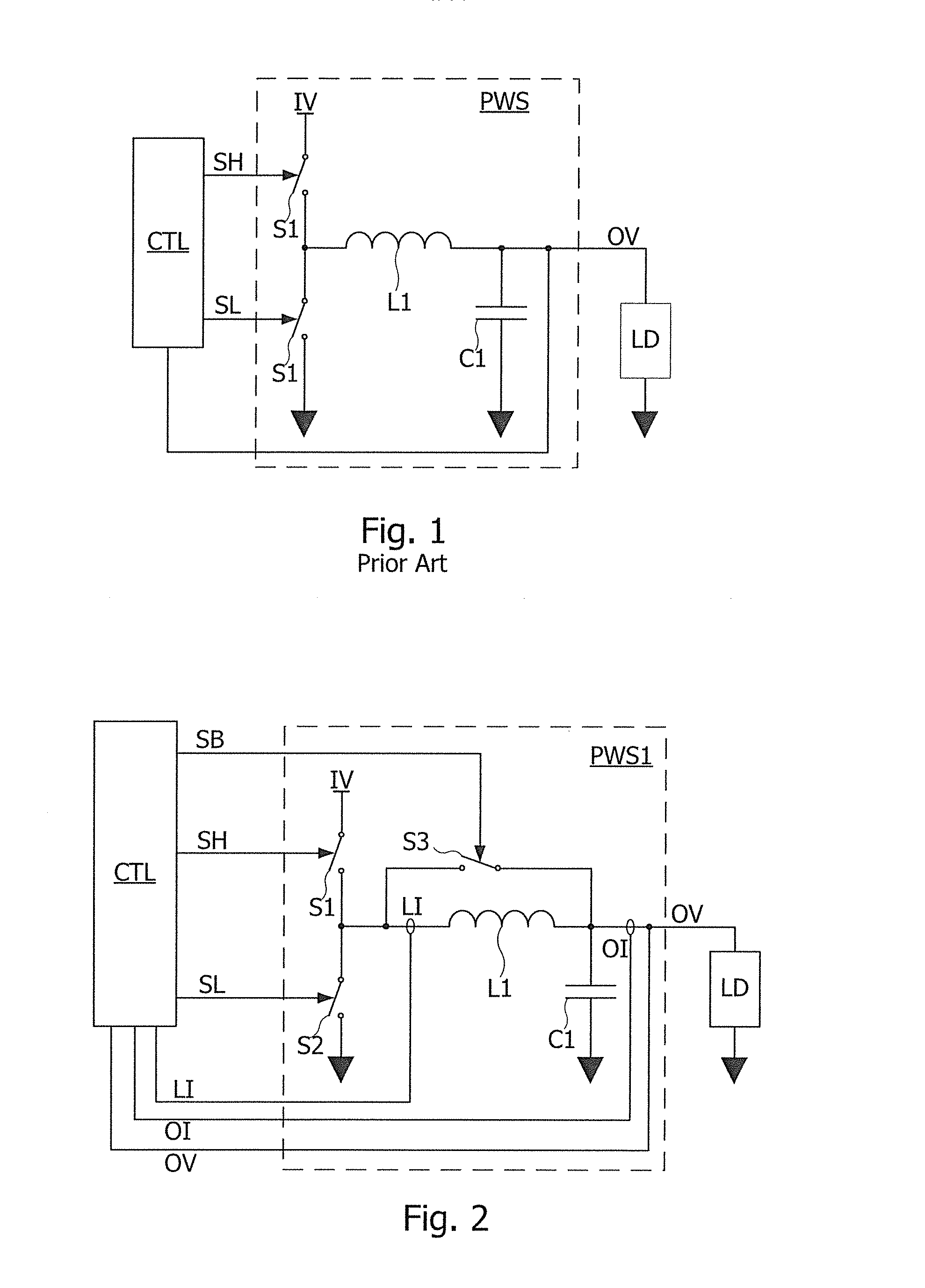
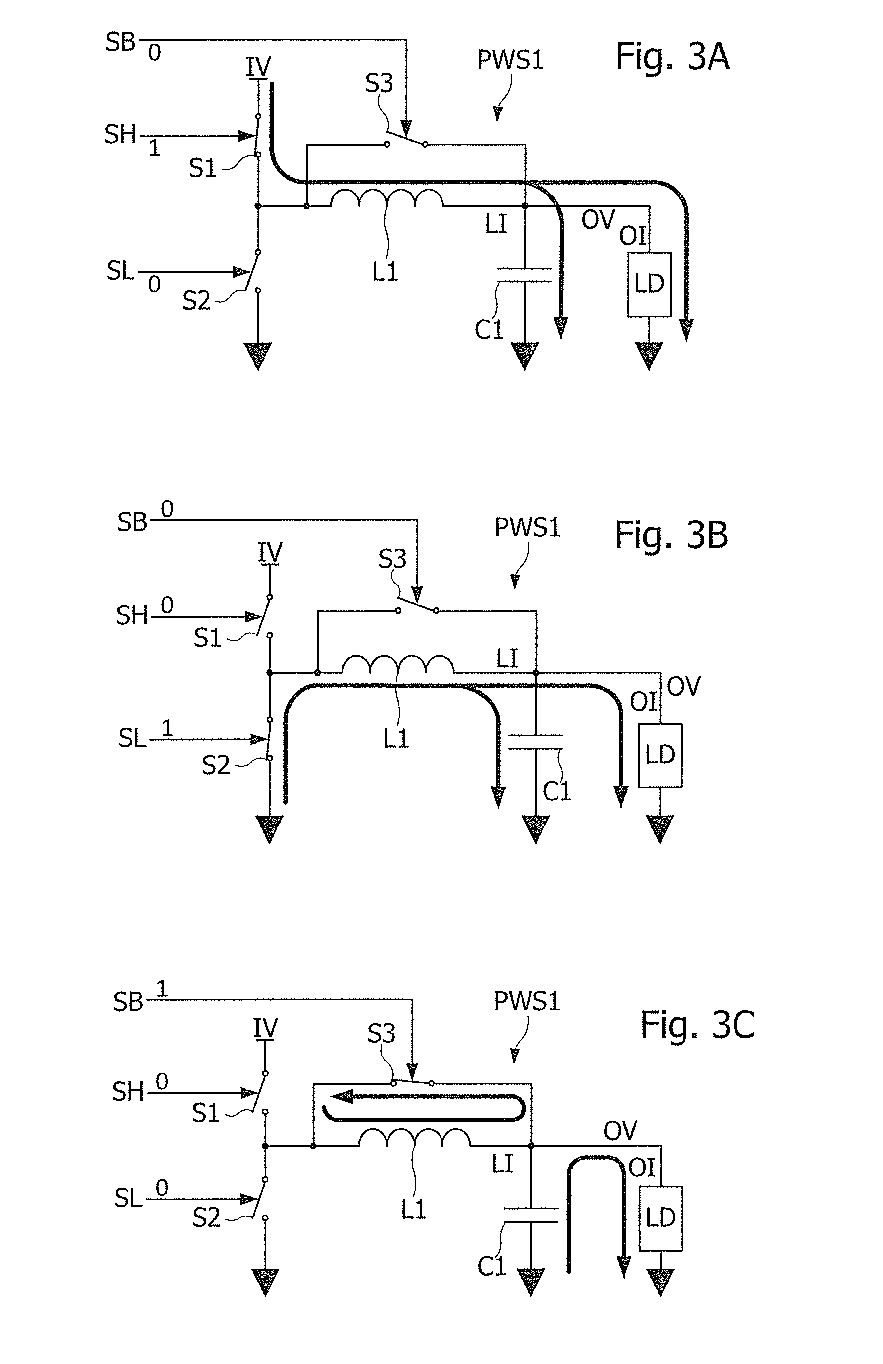
[0046]FIG. 2 is a circuit diagram of a switched power stage according to an embodiment.

[0047]Referring to FIG. 2, a switched power stage PWS1 of this embodiment, which is a step-down type converter, includes switches S1, S2, S3, an inductor L1, a capacitor C1 and a control circuit CTL controlling the switches S1, S2, S3. A first terminal of the switch S1 is connected to a voltage source providing an input voltage IV. A second terminal of switch. S1 is connected to a first terminal of inductor L1, a first terminal of switch S2 and a first terminal of switch S3. A second terminal of switch S2 is connected to the ground. A second terminal of inductor L1 is connected to a second terminal of switch S3, and to a first terminal of capacitor C1, which supplies an output voltage OV to a terminal of a load LD having another terminal connected to the ground. The second terminal of capacitor C1 is connected to the ground. The control circuit CTL may receive a measure signal of output voltage OV...


PUM


Abstract

The disclosure relates to a method of generating an output voltage from a high input voltage and a command signal, the method comprising: providing an inductor having a first terminal and a second terminal linked to a low voltage by a capacitor, the second inductor terminal supplying the output voltage to a load, the low voltage being lower than the high input voltage; and connecting the first inductor terminal either to the high input voltage or to the inductor second terminal, as a function of the command signal.

Description

CROSS REFERENCE TO RELATED APPLICATIONS[0001]This application claims the benefit of the filing date of U.S. Provisional Patent Application No. 61 / 924,349, filed on Jan. 7, 2014, the disclosure of which is incorporated by reference herein.BACKGROUND OF THE INVENTION[0002]The present disclosure generally relates to power stages and voltage converters, and especially to DC-DC converters or switched voltage regulators, capable of varying output voltage and current as a function a processing load of circuits powered by such a converter.DESCRIPTION OF THE RELATED ART[0003]Switched voltage converters are used to convert between differing DC voltages in a wide range of applications. Among switched voltage converters, step-down converters are used to provide a reduced voltage from a higher voltage supply. Typical uses of switched power stages comprise DC-DC converters in particular for battery-operated devices, power stage for class-D amplifiers including audio amplifiers, motor drive circui...

Claims


Application Information

Patent Timeline
IPC IPC(8): H02M3/156H03F3/217
CPCH03F3/217H02M3/156H02M3/158H02M3/1566G05F1/10
Inventor IHS, HASSAN
Owner CHAOYANG SEMICON (SHANGHAI) CO LTD
Why Eureka
Try Eureka