
Tube-fin thermal storage evaporator

Inactive Publication Date: 2015-07-16
HANON SYST
View PDF9 Cites 7 Cited by
  • Summary
  • Abstract
  • Description
  • Claims
  • Application Information

AI Technical Summary

Benefits of technology

The present invention improves a thermal storage evaporator for an air conditioning system for a vehicle. The invention includes a tube and fin arrangement with multiple rows of tubes containing refrigerant tubes and thermal storage tubes containing phase change materials. The fins are interposed between the rows of tubes and in thermal communication with them for receiving a flow of air. The technical effects include improved efficiency and better control over the air conditioning system, particularly in hot or cold temperatures, to provide better driving comfort for the vehicle occupants.

Problems solved by technology

Accordingly, stoppage of the engine, which stops the operation of the compressor of the air conditioning system, affects a temperature of the passenger cabin, especially when the ambient temperature is higher, causing thermal discomfort.
However, these evaporators are not optimal for providing rapid recharging times and longer discharging times, where recharging is the state of the evaporator when the engine is operating (i.e. energy is removed from the PCM) and discharging is the state of the evaporator when the engine is in stop or idle mode (i.e. heat is absorbed by PCM).
For example, a residual cooling of the air by existing evaporators with PCM during an engine off-time may only continue for a limited period of time before the evaporator no longer provides a desired discharge temperature.
Subsequently, after the engine begins operating again, the vehicle may approach another stop or idle shortly after a prior stop or idle without allowing sufficient recharge time for the PCM, thus also resulting in a shorter residual cooling time.
Furthermore, the greater the amount of PCM, the longer the residual cooling time.
However, the structure of the evaporator is typically limited in size to particular air conditioning package requirements based on installation space in the vehicle.
Thus, incorporating additional elements with the evaporator may not be feasible.

Method used


Image

  • Tube-fin thermal storage evaporator
  • Tube-fin thermal storage evaporator
  • Tube-fin thermal storage evaporator

Examples


Embodiment Construction

[0017]The following detailed description and appended drawings describe and illustrate various exemplary embodiments of the invention. The description and drawings serve to enable one skilled in the art to make and use the invention, and are not intended to limit the scope of the invention in any manner. The terms upper, lower, horizontal, and vertical are used with respect to the direction of gravity.

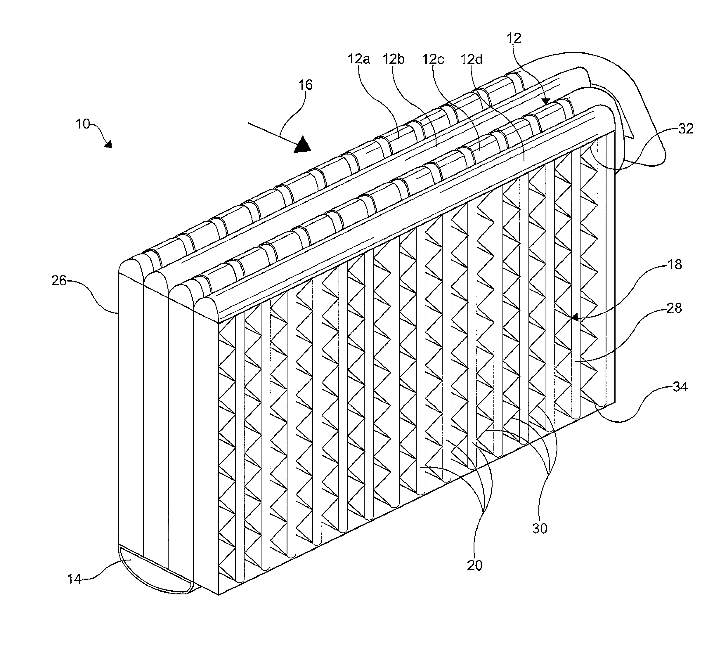
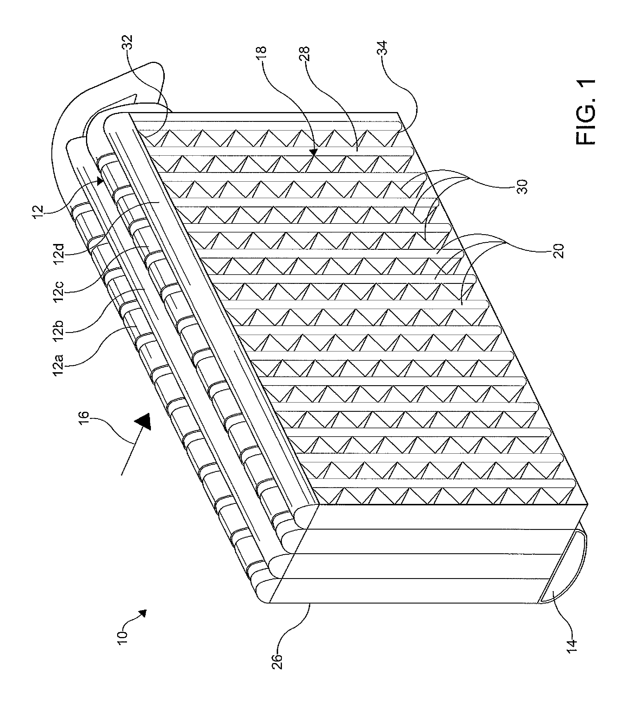
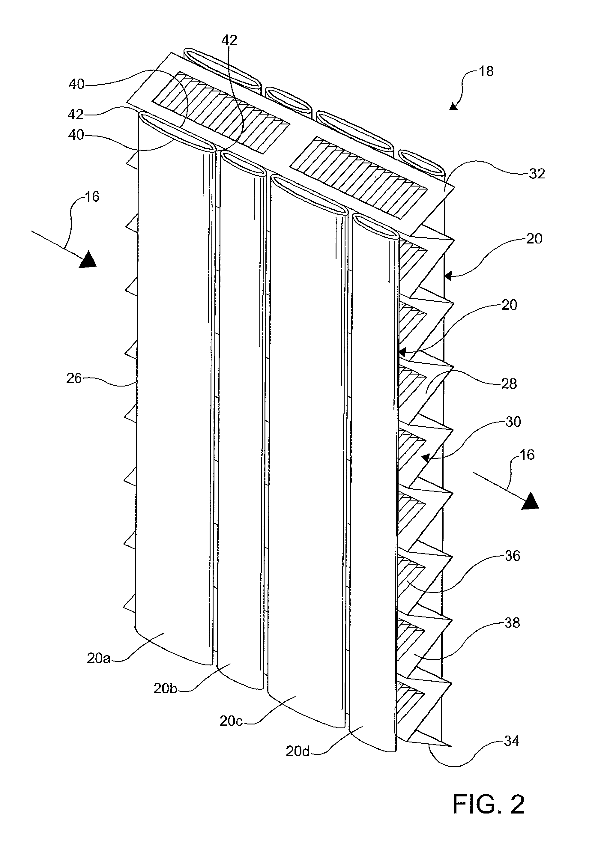
[0018]FIG. 1 illustrates an evaporator 10 of an air conditioning system according to an embodiment of the invention. In the embodiment shown, the evaporator 10 is configured to be a component of a refrigerant system of a motor vehicle (not shown) that includes a compressor that is operably connected to an engine of the motor vehicle. Accordingly, when the engine of the motor vehicle is not operating, the compressor is not operating. It is understood that the evaporator 10 could be used in other systems such as an air conditioning system for a building or an air conditioning system for ...


PUM


Abstract

A tube and fin arrangement of an evaporator for an air conditioning system for a vehicle having a first row of tubes disposed within a flow of air having at least two refrigerant tubes and at least two thermal storage tubes in thermal communication with the at least two refrigerant tubes, each of the thermal storage tubes containing a phase change material. The tube and fin arrangement further includes a fm in thermal communication with the first row of tubes and configured to receive a flow of air therethrough.

Description

FIELD OF THE INVENTION[0001]The present invention relates to a thermal storage evaporator for use in vehicle air conditioning circuits, and more particularly to an arrangement of refrigerant tubes and thermal storage tubes in the evaporator.BACKGROUND OF THE INVENTION[0002]As commonly known, an air conditioning system for a vehicle is driven by engine power of the vehicle. In operation, a refrigerant receives heat from warm air to cool the air and sends cooled or dehumidified air to a passenger cabin of the vehicle. For conventional air conditioning systems, a manual compressor of the air conditioning system runs while the engine of the vehicle is operating. To enhance fuel efficiency, stop-start engine systems can be employed with vehicles that include an internal combustion engine. Additionally, the stop-start engine systems are also employed with vehicles including mild hybrid systems. Mild hybrid systems have a combination of the internal combustion engine and an electric motor....

Claims


Application Information

Patent Timeline
IPC IPC(8): F28F1/12
CPCF28F1/12F28F1/40F28D1/05391F28D20/02F28F1/022F28F1/128F28D2021/0085Y02E60/14
Inventor GOENKA, LAKHI NANDLALHOGARTH, BARTONBYRUM, DOUG
Owner HANON SYST
Learn More