Flowmeter with flow conditioner

a flow conditioner and flowmeter technology, applied in the direction of instruments, volume/mass flow by dynamic fluid flow effect, measurement devices, etc., can solve the problems of poor decision regarding the management of the reservoir, inaccurate valuation of the flow content, and few existing flowmeters being able to accurately measure or derive flow, etc., to reduce the distortion of ultrasonic waves, improve the measurement accuracy or other aspects, and facilitate chordal measurements

Active Publication Date: 2015-07-16
BAKER HUGHES INC
View PDF17 Cites 8 Cited by
  • Summary
  • Abstract
  • Description
  • Claims
  • Application Information

AI Technical Summary

Benefits of technology

[0007]Flowmeters are disclosed herein that include one or more flow path features for improving the measurement accuracy or other aspects of the flowmeter. In some embodiments, the flowmeter includes a measurement section having a non-circular transverse cross-section in which one or more sensors for measuring flow are disposed. The non-circular measurement section can reduce distortion of ultrasonic waves, facilitate chordal measurements with flush-mounted transducers, and reduce the propagation distance between paired transducers. In some embodiments, the flowmeter includes a conditioning section with diametrically opposed longitudinal rib protrusions. The protrusions can reduce swirling flow, direct liquid components of a multi-phase flow towards the sidewalls of the flow path, and guide ballistic particles through the center of the flow path away from sensitive measurement devices.

Problems solved by technology

In situations in which such a multi-phase flow is present, for example at or near a well head where liquid crude oil, natural gas, water, sand, and other materials may be present, few existing flowmeters are able to accurately measure or derive flow.
Such inaccuracies can lead to problems in downstream systems and result in inaccurate valuations of the flow content and poor decisions regarding the management of the reservoir.

Method used


Image

  • Flowmeter with flow conditioner
  • Flowmeter with flow conditioner
  • Flowmeter with flow conditioner

Examples


Embodiment Construction

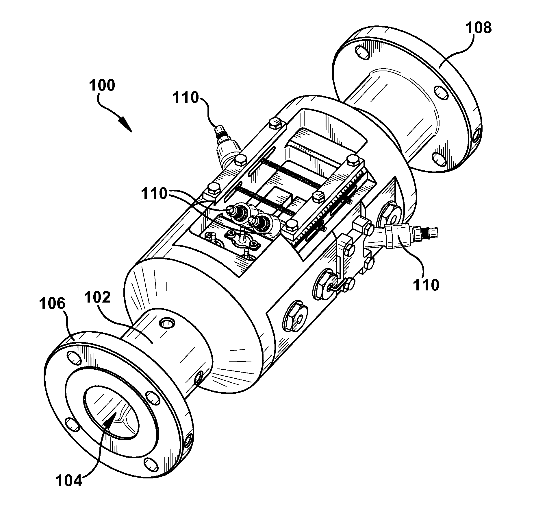
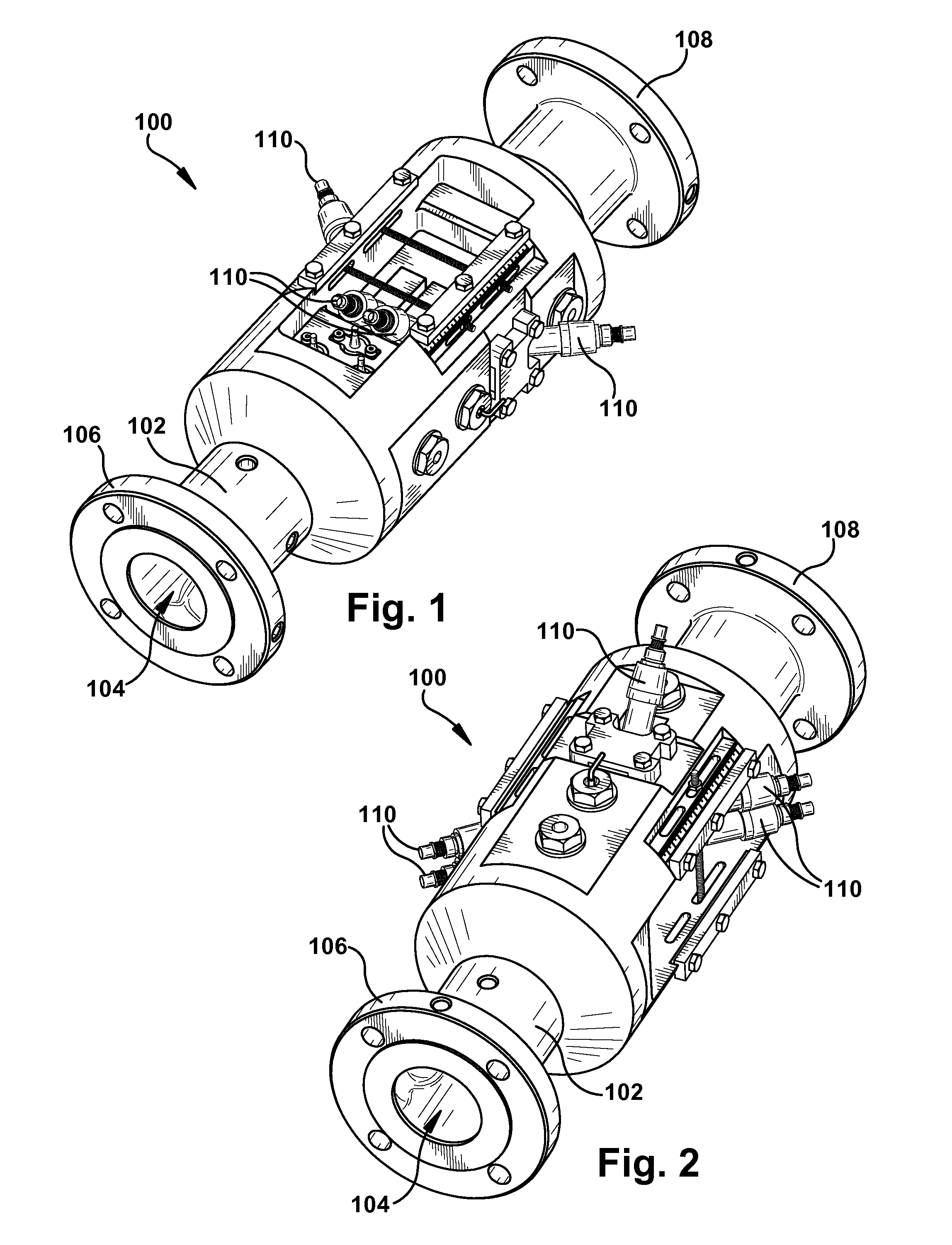
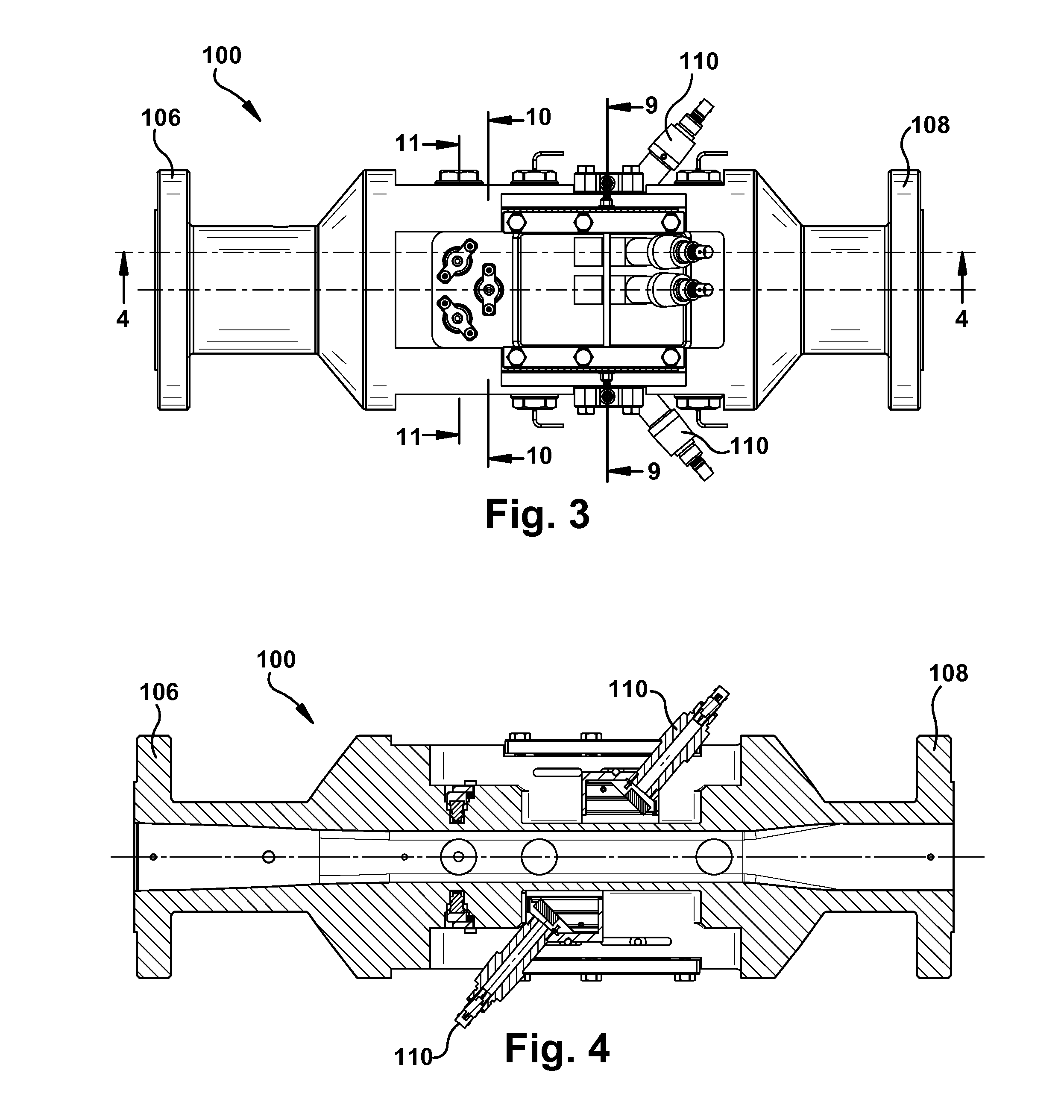
[0035]Flowmeters are disclosed herein that include one or more flow path features for improving the measurement accuracy or other aspects of the flowmeter. In some embodiments, the flowmeter includes a measurement section having a non-circular transverse cross-section in which one or more sensors for measuring flow are disposed. The non-circular measurement section can reduce distortion of ultrasonic waves, facilitate chordal measurements with flush-mounted transducers, and reduce the propagation distance between paired transducers. In some embodiments, the flowmeter includes a conditioning section with diametrically opposed longitudinal rib protrusions. The protrusions can reduce swirling flow, direct liquid components of a multi-phase flow towards the sidewalls of the flow path, and guide ballistic particles through the center of the flow path away from sensitive measurement devices.

[0036]Certain exemplary embodiments will now be described to provide an overall understanding of th...


PUM


Abstract

Flowmeters are disclosed herein that include one or more flow path features for improving the measurement accuracy or other aspects of the flowmeter. In some embodiments, the flowmeter includes a measurement section having a non-circular transverse cross-section in which one or more sensors for measuring flow are disposed. The non-circular measurement section can reduce distortion of ultrasonic waves, facilitate chordal measurements with flush-mounted transducers, and reduce the propagation distance between paired transducers. In some embodiments, the flowmeter includes a conditioning section with diametrically opposed longitudinal rib protrusions. The protrusions can reduce swirling flow, direct liquid components of a multi-phase flow towards the sidewalls of the flow path, and guide ballistic particles through the center of the flow path away from sensitive measurement devices.

Description

FIELD[0001]The subject matter disclosed herein relates generally to systems and methods for measuring flow.BACKGROUND[0002]Flowmeters measure various characteristics of flow within a pipe, for example by using various methods to convert pressure, temperature, and other measured parameters into flow rates or flow volumes. Accurate measurement of these characteristics can be critical, especially in industrial applications such as those in which a flowmeter is used to measure material flow in a chemical processing or petroleum refining plant. Flowmeters must therefore produce highly accurate measurements, even under extreme temperatures, flow rates, and pressures.[0003]In addition, many industrial applications involve transport of materials that include more than one phase of matter (e.g., liquid and gas), also known as a multi-phase flow. In situations in which such a multi-phase flow is present, for example at or near a well head where liquid crude oil, natural gas, water, sand, and ...

Claims


Application Information

Patent Timeline
Patent Type & Authority Applications(United States)
IPC IPC(8): G01F1/66
CPCG01F1/66F15D1/001F15D1/02
Inventor FURLONG, EDWARD RANDALLAO, XIAOLEI SHIRLEYFRIEDEMANN, JOHN DANIELMACKENZIE, COLIN JAMESNAGARANAVILE, NATARAJA ASWATHANARAYANA
Owner BAKER HUGHES INC
Why Eureka
Try Eureka