Radar apparatus

a technology of radar and apparatus, applied in the field of radar equipment, can solve problems such as the reduction of object detection accuracy, and achieve the effect of improving the accuracy of object detection, avoiding side lobes or grating lobes occurring, and correcting estimations

Active Publication Date: 2015-07-16
PANASONIC CORP
View PDF11 Cites 34 Cited by
  • Summary
  • Abstract
  • Description
  • Claims
  • Application Information

AI Technical Summary

Benefits of technology

[0013]According to the present disclosure, incorrect estimations caused by side lobes or grating lobes occurring in the azimuth direction can be reduced to improve the accuracy of object detection in estimation of the azimuth angle of an object using a receive array antenna.

Problems solved by technology

Since it is difficult with the vehicle travel status detection device disclosed in Japanese Unexamined Patent Application Publication No. 2010-043960 to distinguish between a reflected wave signal from the target and a side lobe or grating lobe, an incorrect estimation of the azimuth angle of the target can occur, leading to a reduction in the accuracy of object detection.

Method used


Image

  • Radar apparatus
  • Radar apparatus
  • Radar apparatus

Examples


first embodiment

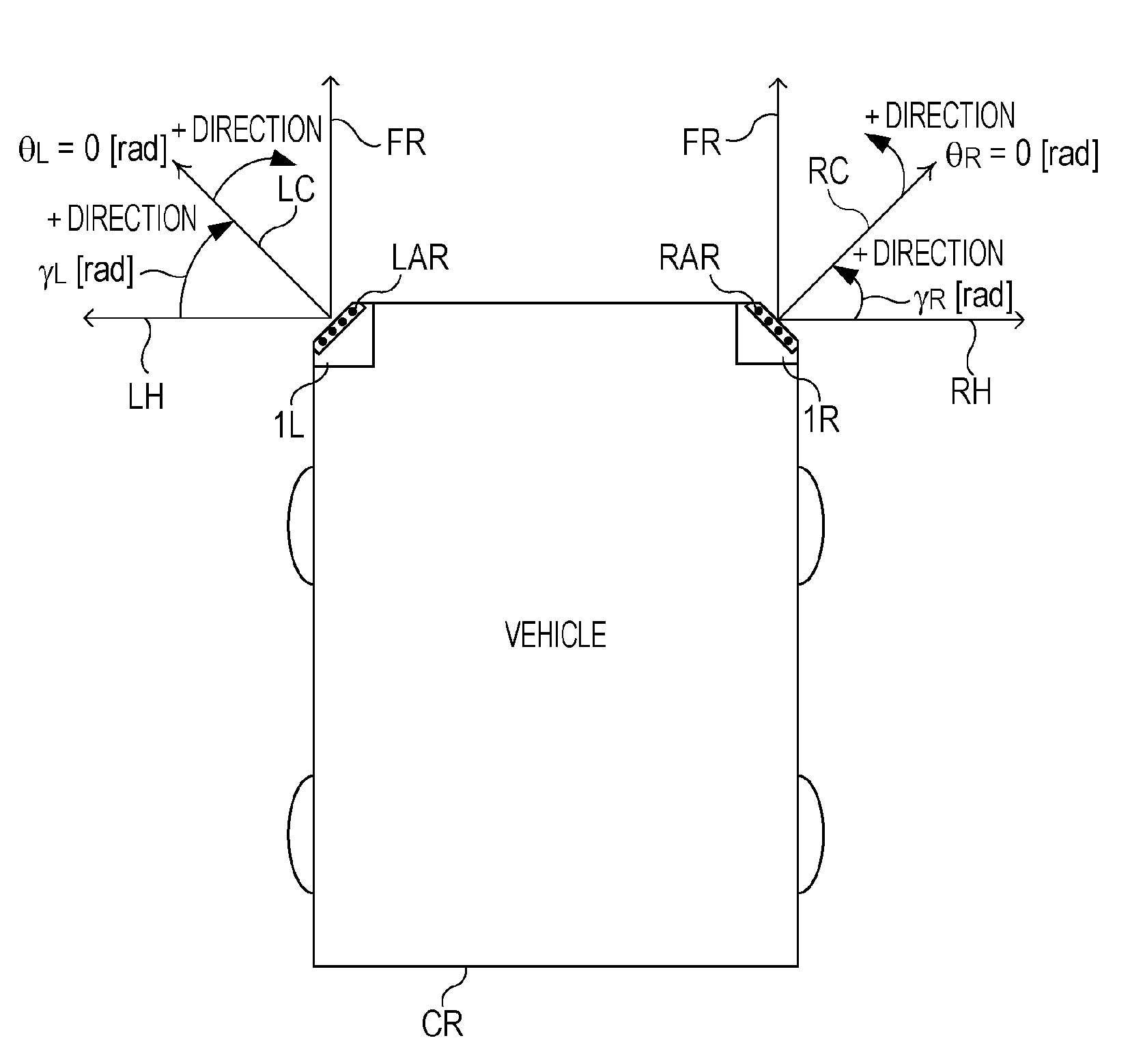
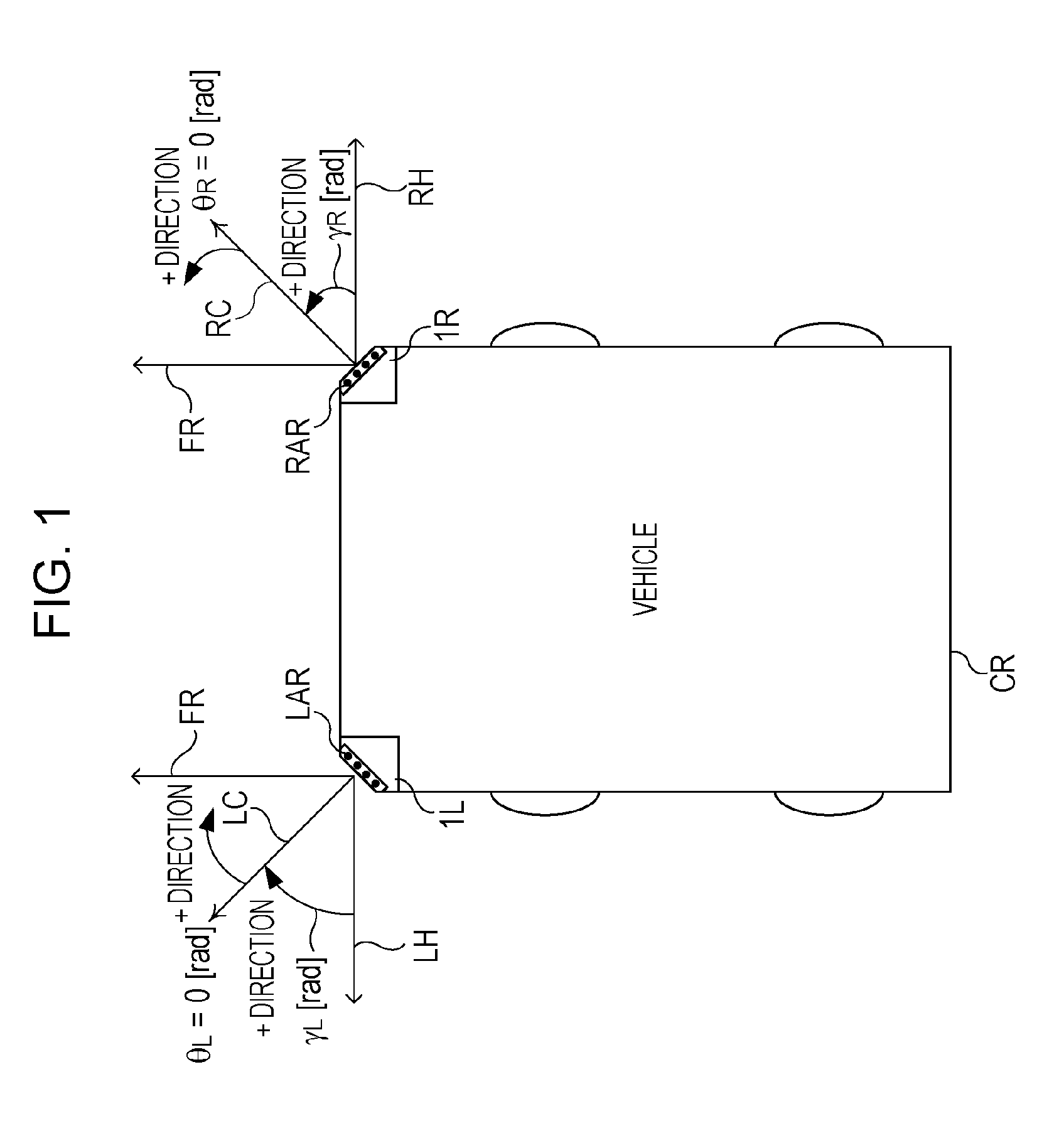
[0030]FIG. 1 is a diagram illustrating the relationship between a vehicle coordinate system and a radar coordinate system. In this embodiment, two radar apparatuses 1L and 1R are installed, for example, on the front lateral sides of the vehicle CR with respect to the front direction FR thereof; however two radar apparatuses may be installed on the rear lateral sides of the vehicle CR instead.

[0031]In FIG. 1, the installation angle γL of multiple receive antennas (hereinafter referred to as an array antenna) of the radar apparatus 1L is the angle formed between the left side direction LH of the vehicle CR (the reference of left lateral radar installation angle) and the vertical direction LC of the aperture plane of the array antenna LAR of the radar apparatus 1L. For the installation angle γL of the array antenna LAR of the radar apparatus 1L, the clockwise direction is the normal direction (γL>0) relative to the left side direction LH of the vehicle CR. Also, the clockwise direction...


PUM


Abstract

A radar apparatus is installed in a vehicle that moves along its direction of travel. A radar transmission unit transmits a high frequency radar transmission signal from a transmit antenna in each transmit period. In a radar reception unit, antenna system processing units each generate a correlation vector by computing the correlation between reflected wave signal from a stationary object or a moving object and the radar transmission signal. A Doppler frequency-azimuth conversion unit converts Doppler frequencies into the components of an azimuth in which the stationary object is present using an estimated vehicle speed vector for the vehicle. A stationary object azimuth estimation unit generates the power profile of the reflected wave signal using the correlation vector and a direction vector corresponding to the components of the azimuth in which the stationary object is present.

Description

CROSS REFERENCES TO RELATED APPLICATIONS[0001]This application claims priority to Japanese Patent Applications No. 2014-005436, filed on Jan. 15, 2014, and No. 2014-177635, filed on Sep. 2, 2014, the contents of each of which are hereby incorporated by reference.BACKGROUND[0002]1. Technical Field[0003]The present disclosure relates to a radar apparatus for installation in a mobile unit including a vehicle.[0004]2. Description of the Related Art[0005]A radar apparatus is known in which reflected wave signals reflected by a target (hereinafter referred to as an object or target object) are received by an array antenna and the phase differences in the received signals received by the individual receive antennas are measured to estimate the direction in which the reflected wave signals from the object arrive over a wide angle range.[0006]A conventional technique in which a radar apparatus which is capable of measurement over a wide angle range is installed in a mobile unit (a vehicle fo...

Claims


Application Information

Patent Timeline
Patent Type & Authority Applications(United States)
IPC IPC(8): G01S7/02G01S13/02G01S13/931
CPCG01S13/02G01S7/02G01S7/2813G01S7/411G01S7/414G01S7/415G01S13/26G01S13/325G01S13/343G01S13/582G01S13/931G01S7/2923G01S2013/93274G01S2013/93271G01S7/2886
Inventor KISHIGAMI, TAKAAKINAKAGAWA, YOICHI
Owner PANASONIC CORP
Why Eureka
Try Eureka