Proximity-interrogative smart fob switching of electrical device

a technology of electrical devices and proximity, applied in the direction of individual entry/exit registers, registers, instruments, etc., can solve the problems of reducing the reception capability of the receiving device, reducing the signal strength of the fob, and reducing the proximity

Inactive Publication Date: 2015-07-16
DOUBLE SECURED
View PDF12 Cites 19 Cited by
  • Summary
  • Abstract
  • Description
  • Claims
  • Application Information

AI Technical Summary

Benefits of technology

[0007]Accordingly, embodiments of the invention are directed to proximity-interrogative fob that substantially obviates one or more of the problems due to limitations and disadvantages of the related art.

Problems solved by technology

On the other hand, a decrease in the signal strength of the fob or a decrease in reception capability of the receiving device will decrease proximity.
Thus, the transmitted activation code can be stolen and subsequently used inappropriately with the receiving device to actuate an electrical device.

Method used


Image

  • Proximity-interrogative smart fob switching of electrical device
  • Proximity-interrogative smart fob switching of electrical device
  • Proximity-interrogative smart fob switching of electrical device

Examples


Embodiment Construction

[0025]Reference will now be made in detail to the preferred embodiments of the invention, examples of which are illustrated in the accompanying drawings. Reference will now be made in detail to the preferred embodiments of the invention, examples of which are illustrated in the accompanying drawings. The invention may, however, be embodied in many different forms and should not be construed as being limited to the embodiments set forth herein; rather, these embodiments are provided so that this disclosure will be thorough and complete, and will fully convey the concept of the invention to those skilled in the art. In the drawings, the thicknesses of layers and regions are exaggerated for clarity. Like reference numerals in the drawings denote like elements.

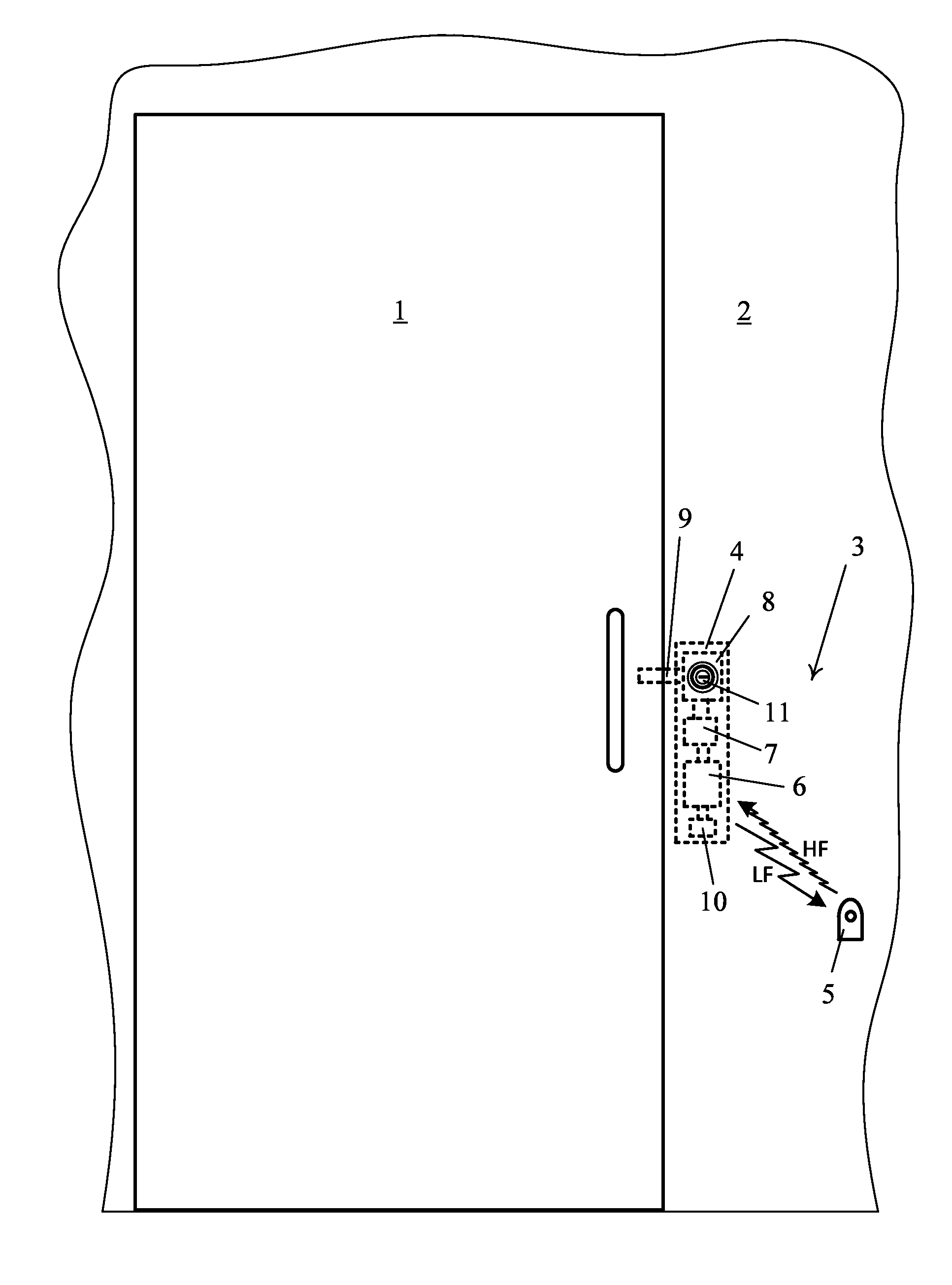
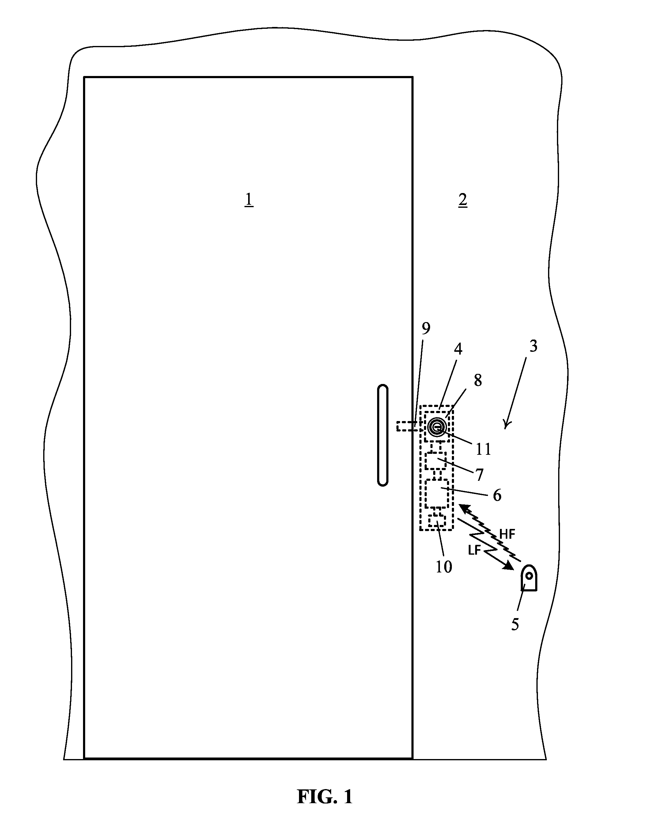
[0026]FIG. 1 is an illustration of a door lock in a wall adjacent the door and a smart fob according to an embodiment of the invention. As shown in FIG. 1, a door 1 in wall 2 is secured by a locking system 3 having a locking devic...


PUM


Abstract

A smart fob for interfacing with a smart module includes: a low frequency receiver for receiving a first password and a smart module ID number in a low frequency signal; a memory for storing a registration number with which the smart fob is registered to the smart module; a smart module ID detector connected to the low frequency receiver for waking-up the smart fob if the smart module ID number in the low frequency signal matches the smart module ID number in the memory; a processor for providing a second password derived from the first password and the registration number of the smart fob; and a high frequency transmitter for transmitting the second password in a high frequency signal.

Description

BACKGROUND OF THE INVENTION[0001]1. Field of the Invention[0002]Embodiments of the invention relate to switching of an electrical device, and more particularly, to switching an electrical device in the proximity of a fob. Although the embodiments of the invention are suitable for a wide scope of applications, it is particularly suitable for activating an electric lock or for turning-on electrical power only when a specific fob is in proximity and de-activating the electric lock or turning-off electrical power when the specific fob is not in proximity.[0003]2. Discussion of the Related Art[0004]In general, a proximity switching system has a receiving device and a fob that can transmit a wireless signal. A fob has to be sufficiently close to the receiving device such that a wireless signal transmitted from the fob can be received by the receiving device. The range within which the receiving device can receive wireless signals of the fob is the proximity. Accordingly, an increase in th...

Claims


Application Information

Patent Timeline
Patent Type & Authority Applications(United States)
IPC IPC(8): G07C9/00
CPCG07C9/00111G07C9/00309G07C2009/00373G07C2009/00793G07C2209/61G07C9/28
Inventor HONG, SUKKILEE, YONG MOO
Owner DOUBLE SECURED
Why Eureka
Try Eureka