Method and apparatus for dermatological treatment

a dermatological treatment and apparatus technology, applied in the field of cosmetic methods and, can solve the problems of increased skin tightness, more rejuvenation, and longer healing time, so as to reduce healing or recovery time, facilitate healing, and reduce healing time

Inactive Publication Date: 2015-07-23
THE GENERAL HOSPITAL CORP
View PDF5 Cites 11 Cited by
  • Summary
  • Abstract
  • Description
  • Claims
  • Application Information

AI Technical Summary

Benefits of technology

[0012]According to exemplary embodiments of the present disclosure, method and apparatus can be provided for ablative fractional skin resurfacing that includes forming a small ablated hole (e.g., less than 1 mm in diameter, or less than about 0.5 mm) and then directing one or more further pulses into the hole sequentially to generate further tissue coagulation with little or no further tissue ablation, followed by one or more pulses to ablate a portion of the coagulated tissue. Such pulses can be generated using an ablative laser (e.g., a CO2 laser, a CO laser, an erbium laser, for example, an Er:YAG or Er:YSGG laser, e.g., a CO2 laser, a CO laser, an erbium laser such as an Er:YAG or Er:YSGG laser, and / or another type of YAG laser such as a Tm:YAG, Ho:YAG, or a Nd:YAG laser, or the like), and optionally by using an additional non-ablative laser. Parameters of the laser pulses can be selected and controlled using, e.g., a control arrangement, to provide a plurality of pulses onto a single target location on the skin to achieve these effects.
[0015]Individual holes can be further processed by directing one or more further pulses of energy into the hole. Various sequences of HA pulses, MA pulses, and / or NA pulses can be provided to generate particular effects in tissue. For example, after a deep hole is ablated using an HA or predominantly ablative MA pulse, one or more NA pulses and / or predominantly coagulative MA pulses can then be directed into the hole to coagulate more tissue within the hole. A portion of this coagulated tissue can then be ablated by directing one or more MA or HA pulses into the hole. This exemplary procedure can optionally be repeated a number of times in a single hole to alternately form coagulated tissue within the hole and then remove at least a portion of it by ablation. Such exemplary pulse sequences may reduce healing or recovery times, for example, by directing further pulses of energy (EMR) into each ablated hole without a significantly increase in the hole depth or width. Rejuvenation effects (e.g. new collagen growth and / or skin tightening) associated with each such hole may be comparable or greater than that resulting from, e.g., a single ablative pulse having the same total energy as the sequence of pulses.
[0016]According to further exemplary embodiments of the present disclosure, a plurality of MA and / or NA pulses can be directed into the ablated hole after the ablative pulses to generate more coagulated tissue therein, such that the hole can be at least partially filled with coagulated tissue. In this exemplary manner, a larger amount of tissue removal and shrinkage can be generated in each hole without enlarging the hole dimensions, which may facilitate healing and / or reduce healing times, and can also lead to enhanced tissue rejuvenation effects for the procedure.
[0019]According to still further exemplary embodiments of the present disclosure, a method can be provided for directing pulsed electromagnetic energy onto biological tissue. The exemplary method can direct at least one ablative pulse of EMR onto a particular location on the tissue to ablate a hole therein, then direct at least one further pulse of EMR onto the same location, e.g., into the ablated hole, to generate tissue coagulation therein, and then direct at least one further EMR pulse onto the same location to ablate at least a portion of the coagulated tissue formed. In additional exemplary embodiments of the present disclosure, the exemplary method can facilitate directing at least one further non-ablative or mildly ablative pulse of EMR onto the same location (e.g., into the hole) to coagulate further tissue in the hole and at least partially fill the hole.

Problems solved by technology

Higher areal fractions can result in increased skin tightening, more rejuvenation and / or other desirable cosmetic effects, but healing times may be longer because of the larger amount of epidermal tissue that is thermally damaged or removed.
Ablation can occur when the EMR is of sufficiently high intensity, sufficiently absorbed by the tissue, and applied in a sufficiently short time to vaporize a portion of the tissue, which can lead to formation of holes in the tissue and / or removal of further tissue in an existing hole.
Such milder thermal damage can “cook” the tissue, e.g., coagulate tissue and / or denature proteins such as collagen, which may result in local death of some cells and damage to other cells.
EMR at certain weakly-absorbed wavelengths such as, e.g., some diode lasers, may be better suited for thermally damaging tissue and may not be capable of generating sufficient intensity of absorbed EMR to ablate tissue under typical operating conditions.

Method used


Image

  • Method and apparatus for dermatological treatment
  • Method and apparatus for dermatological treatment
  • Method and apparatus for dermatological treatment

Examples


example 1

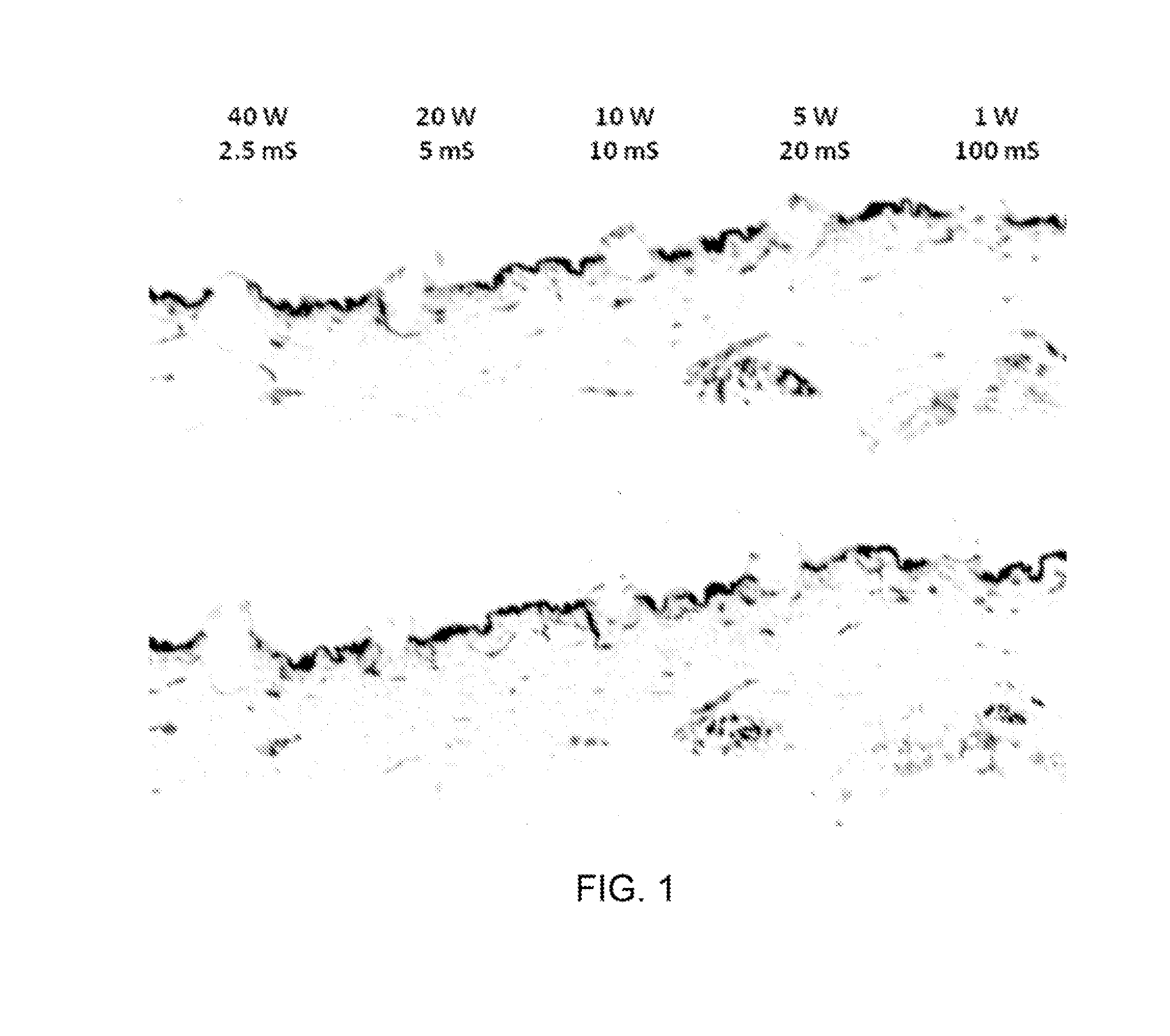
[0063]Two cross-sectional images of a histological sample showing the effects of two exemplary laser pulse sequences on ex vivo skin tissue are shown in FIG. 4. The skin sample was irradiated with pulses generated by a CO2 laser. The holes shown in FIG. 3 were generated by sequences of three pulses having the powers and durations indicated below the cross-sectional images. For example, the two rightmost holes shown in FIG. 3 were formed by first directing an HA pulse onto the tissue (40 W, 2 ms duration), followed by an MA pulse (5 W, 2 ms duration), and finally an NA pulse (1 W, 10 ms duration) onto the same location. The time interval between pulses was about 10 seconds, although much shorter pulse intervals can be used.

[0064]Similarly, the two leftmost holes shown in FIG. 4 were generated by the pulse sequence denoted below these holes. First, an NA pulse with a power of 1 W and duration of 10 ms was directed onto the tissue. Next, an MA pulse having 5 W power and 2 ms duration w...

example 2

[0067]A Lumenis UltraPulse system with AcuScan120 handpiece (Lumenis Surgical) that includes a controllable CO2 laser was modified with a controller arrangement. The controller arrangement facilitated programming and control of particular pulse sequences in accordance with exemplary embodiments of the present disclosure. 10 sequences of energy pulses (A2-J2) were directed into different locations on a 2 cm×2 cm sample of previously-frozen human abdominal skin.

[0068]The first three sequences (A2-C2) included only ablative 60 W pulses, with a total energy of 100 mJ per sequence. Pulse energies and durations for these ablative sequences are specified in Table 1 below. The exemplary system was programmed in accordance with embodiments of the present disclosure to irradiate the tissue with five further sequences of pulses (D2-H2), with a different location being irradiated by each pulse sequence. Pulse energies and durations for these five sequences, which include a mix of 60 W pulses th...


PUM


Abstract

Exemplary methods and devices can be provided for fractional resurfacing of skin that include formation of a plurality of small holes, e.g., having widths less than about 1 mm or 0.5 mm, using one or more pulses of ablative electromagnetic radiation (EMR), e.g., optical energy. One or more pulses of substantially non-ablative can then be directed into the ablated holes to coagulate tissue therein, followed by at least one further ablative pulse of EMR to ablate and remove some of the coagulated tissue. Optionally, one or more further pulses of non-ablative EMR can then be directed into the hole to reduce the hole depth. Such procedures and device can provide reduced healing times and / or enhanced rejuvenation effects.

Description

CROSS-REFERENCE TO RELATED APPLICATION(S)[0001]The present application relates to and claims priority from U.S. Provisional Patent Application Ser. No. 61 / 681,992 filed Aug. 10, 2012, the present disclosure of which is incorporated herein by reference in its entirety.TECHNICAL FIELD[0002]The present disclosure relates to cosmetic methods and apparatus for fractional photothermolysis of skin and other tissues, in which a plurality of energy pulses having different properties can be provided onto a single location on the tissue, so as to form a hole therein, coagulate tissue within the hole, and then ablate at least a portion of the coagulated tissue.BACKGROUND INFORMATION[0003]Fractional skin resurfacing relates to a cosmetic procedure where small regions of thermal damage are formed in skin tissue using electromagnetic energy, e.g. electromagnetic radiation (EMR), such as a laser beam. Each region is preferably small, e.g., less than 1 mm in diameter or less than 0.5 mm in diameter,...

Claims


Application Information

Patent Timeline
Patent Type & Authority Applications(United States)
IPC IPC(8): A61B18/20
CPCA61B18/203A61B2018/00589A61B2018/0047A61B2017/00761A61B2018/00577
Inventor MANSTEIN, DIETERKOSITRATNA, GARUNA
Owner THE GENERAL HOSPITAL CORP
Why Eureka
Try Eureka