
Securing a TMS coil to the patient's head

a technology tms coil, which is applied in the field of transcranial magnetic stimulation, can solve the problems of difficulty in maintaining such proper location and orientation for the technician, and achieve the effects of convenient conduct, convenient tms study, and reduced physical effor

Active Publication Date: 2015-07-23
UNIV OF FLORIDA RES FOUNDATION INC
View PDF14 Cites 9 Cited by
  • Summary
  • Abstract
  • Description
  • Claims
  • Application Information

AI Technical Summary

Benefits of technology

The patent text describes a support structure for a TMS coil that can be attached to a treadmill or chair for use while the patient is exercising or relaxing. This structure helps to alleviate the weight burden on the patient while still providing effective treatment. Overall, this invention makes it easier to use the TMS coil while providing more comfort for the patient.

Problems solved by technology

This is problematic because the TMS coil and its attached cable weigh approximately 9 pounds (approximately 4 kilograms) and the technician is challenged to keep the TMS coil properly targeted, i.e. properly located on the patient's head and properly oriented towards the brain region of interest.
Additionally, it can be difficult for the technician to maintain such proper location and orientation when the patient's head moves.

Method used


Image

  • Securing a TMS coil to the patient's head
  • Securing a TMS coil to the patient's head
  • Securing a TMS coil to the patient's head

Examples


Embodiment Construction

[0017]In the Figures, the same element is always indicated by the same reference numeral. The Figures are not to scale, and details may be enlarged or eliminated for clarity. Corresponding elements in the various embodiments are indicated using primed reference numerals.

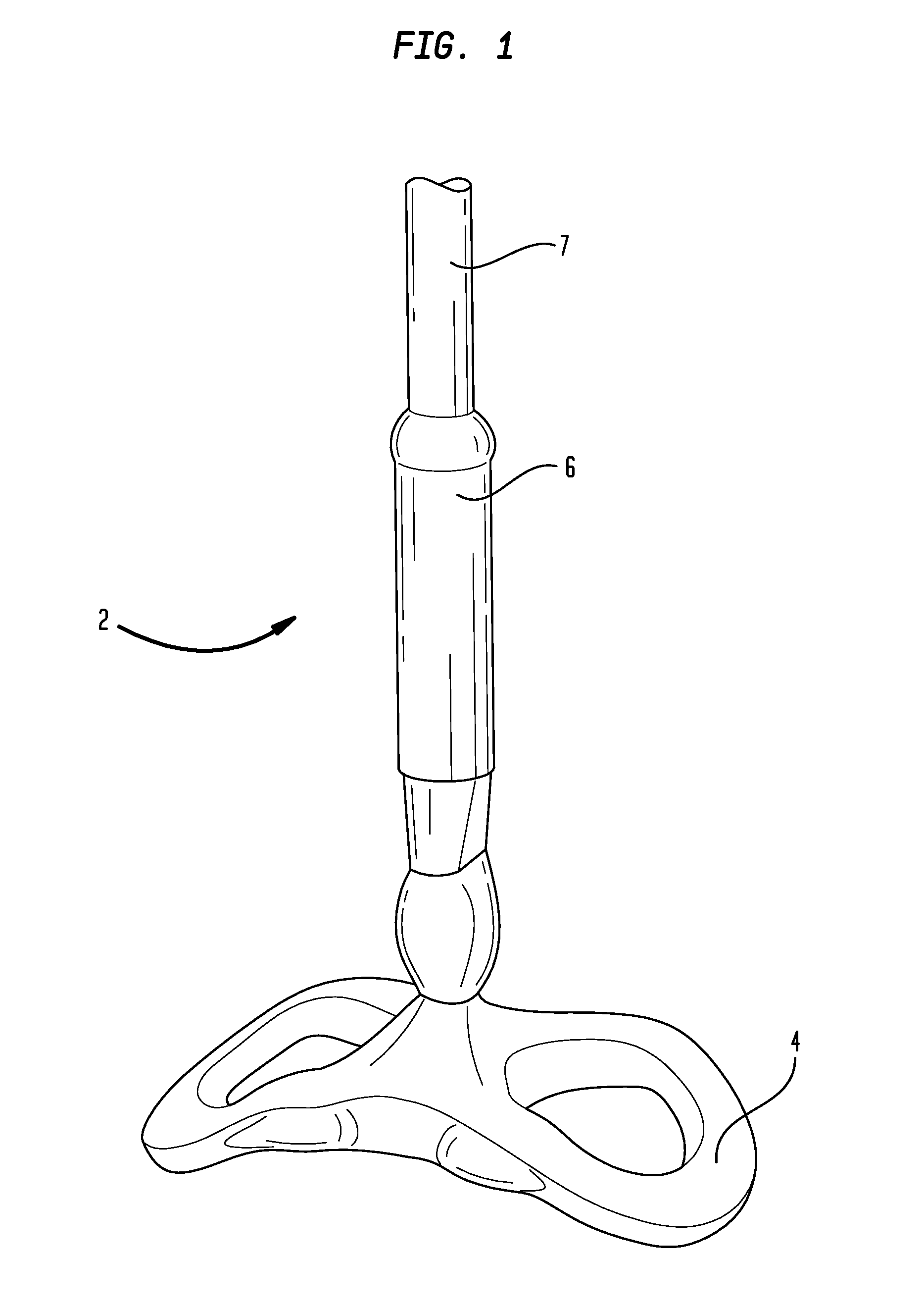
[0018]FIG. 1 shows a conventional TMS coil 2, having an antenna 4 at one end. An electric cable 7 is connectable to the handle 6 of the TMS coil 2. A TMS study of a patient (not shown in FIG. 1) is carried out by appropriately positioning and orienting the antenna 4 with respect to the head of the patient, directing current pulses through the antenna 4, and detecting and mapping the brain activity that is evoked.

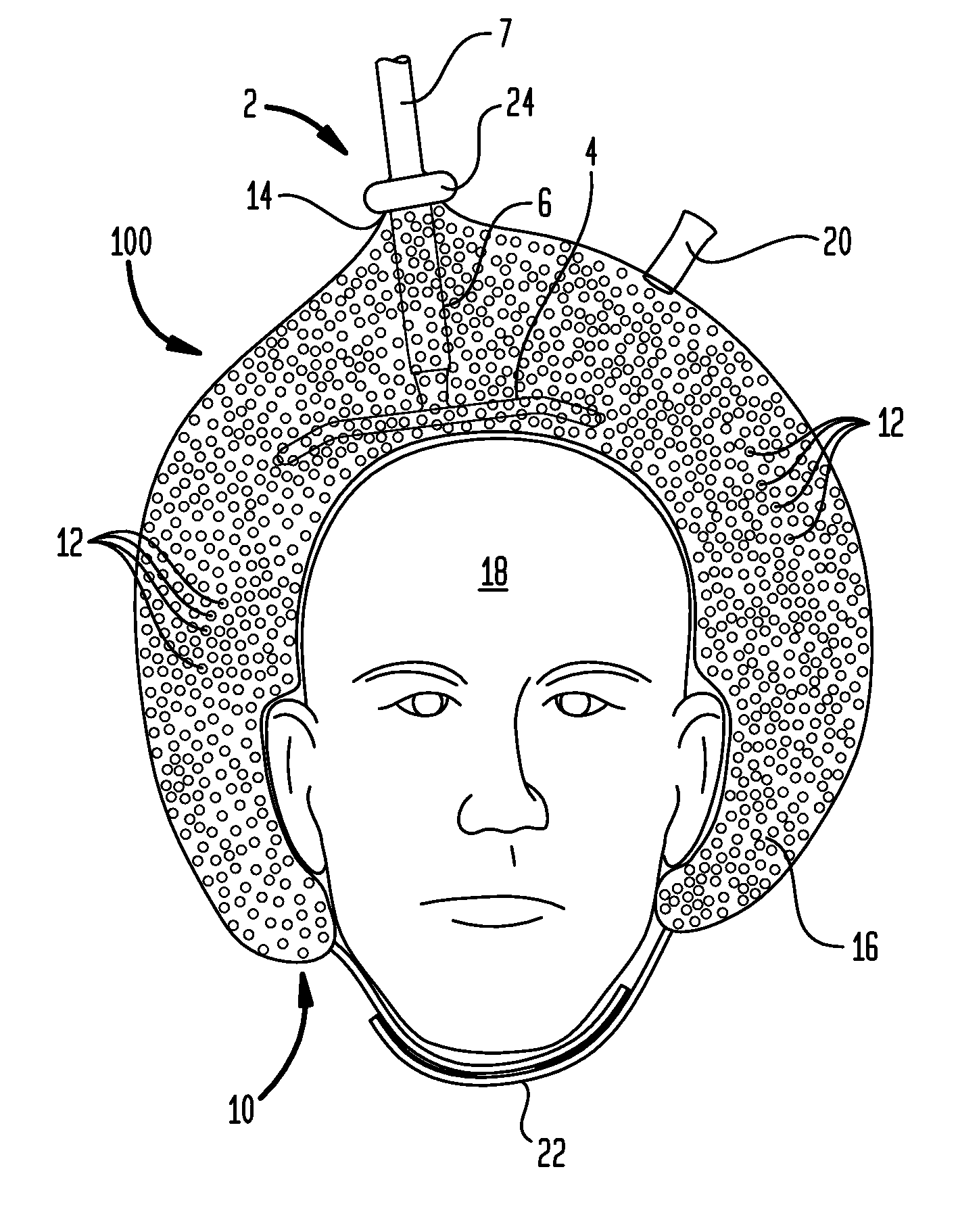
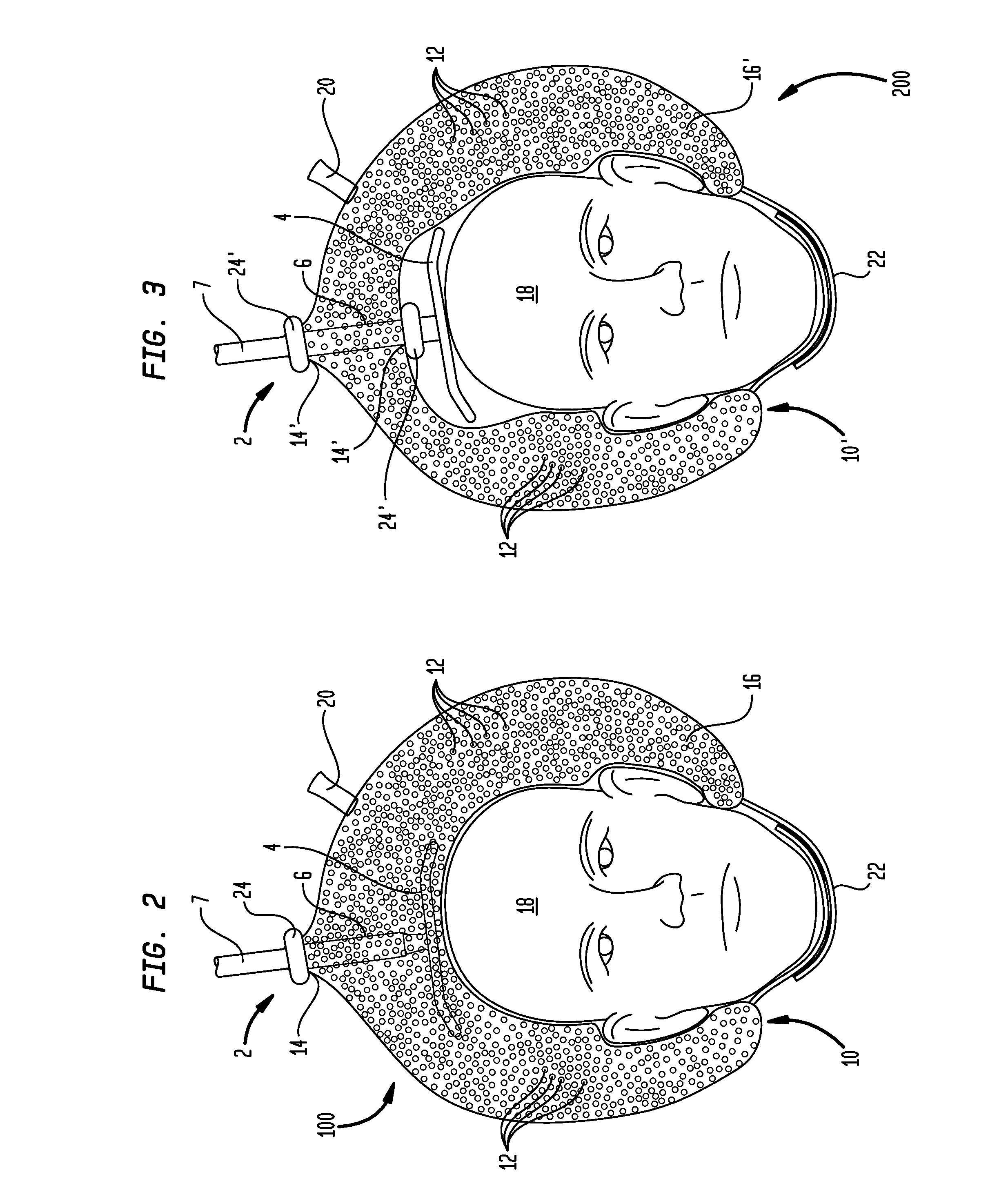
[0019]FIG. 2 shows a first preferred embodiment of the invention. A helmet generally indicated by reference numeral 100 has a flexible and airtight sack 10, which may be made of nylon or any other material that can withstand repeated cleaning. The material used for the sack 10 is not part of the invention. Th...


PUM


Abstract

A helmet is used to detachably secure a TMS coil to the head of a patient. The helmet has a flexible sack containing a multiplicity of beads and also has a valve that permits air to enter and to be withdrawn from the interior volume of the sack. The handle of the TMS coil is inserted into the helmet, and the helmet is placed upon the head of a patient. Withdrawing air from the interior volume of the sack through the valve causes the sack to shrink and compresses the beads into a compact mass that conforms to the shape of the patient's head. Maintaining the vacuum causes the sack to retain its shape, making it possible to hold the helmet and TMS coil in proper position during a TMS study.

Description

STATEMENT REGARDING FEDERALLY SPONSORED RESEARCH OR DEVELOPMENT[0001]This invention was made with government support under CTSA grant UL1 TR000064 awarded by the National Institutes of Health and the National Center for Research Resources. The government has certain rights in the invention.BACKGROUND OF THE INVENTION[0002]The invention relates to transcranial magnetic stimulation (TMS), and more particularly relates to TMS coils. In its most immediate sense, the invention relates to securing a TMS coil to a patient's head.[0003]In TMS, a current pulse (or a series of current pulses) is directed through a coil (a “TMS coil”) that is positioned adjacent the head of a human patient. Each current pulse causes the TMS coil to produce an intense magnetic field. This magnetic field induces changes in the state of polarization of neurons in the patient's brain, which changes in turn evoke activity in the brain. Measurement of this activity makes it possible to e.g. determine the functions o...

Claims


Application Information

Patent Timeline
IPC IPC(8): A61N2/00A61N2/02
CPCA61N2/006A61N2/002A61N2/02
Inventor TOPP, ERIC L.PATTEN, CAROLYNN
Owner UNIV OF FLORIDA RES FOUNDATION INC
Learn More