Hydrostatic Drive System In A Closed Circuit

a drive system and closed circuit technology, applied in the direction of fluid gearings, gearing control, couplings, etc., can solve the problems of large space occupation, large design effort and expense, and two individual drive units occupying a large amount of space, so as to achieve simple and economical manner

Inactive Publication Date: 2015-07-23
LINDE HYDRAULICS
View PDF1 Cites 11 Cited by
  • Summary
  • Abstract
  • Description
  • Claims
  • Application Information

AI Technical Summary

Benefits of technology

[0053]The invention further relates to a vehicle with a hydrostatic drive system of the invention. With the double drive unit that has two flows and two separate delivery flows and can be connected with the hydraulic connectio

Problems solved by technology

This design entails a great deal of construction effort and expense and occupies a large amount of space, because each of the two individual drive units has a separate housing and a separate shaft with the corresponding shaft bearing in the respective housing of the corresponding individual drive unit.
The shaft required for the coupling of the two individual drive units or the transmission required for the coupling of the two individual drive unit

Method used


Image

  • Hydrostatic Drive System In A Closed Circuit
  • Hydrostatic Drive System In A Closed Circuit
  • Hydrostatic Drive System In A Closed Circuit

Examples


Embodiment Construction

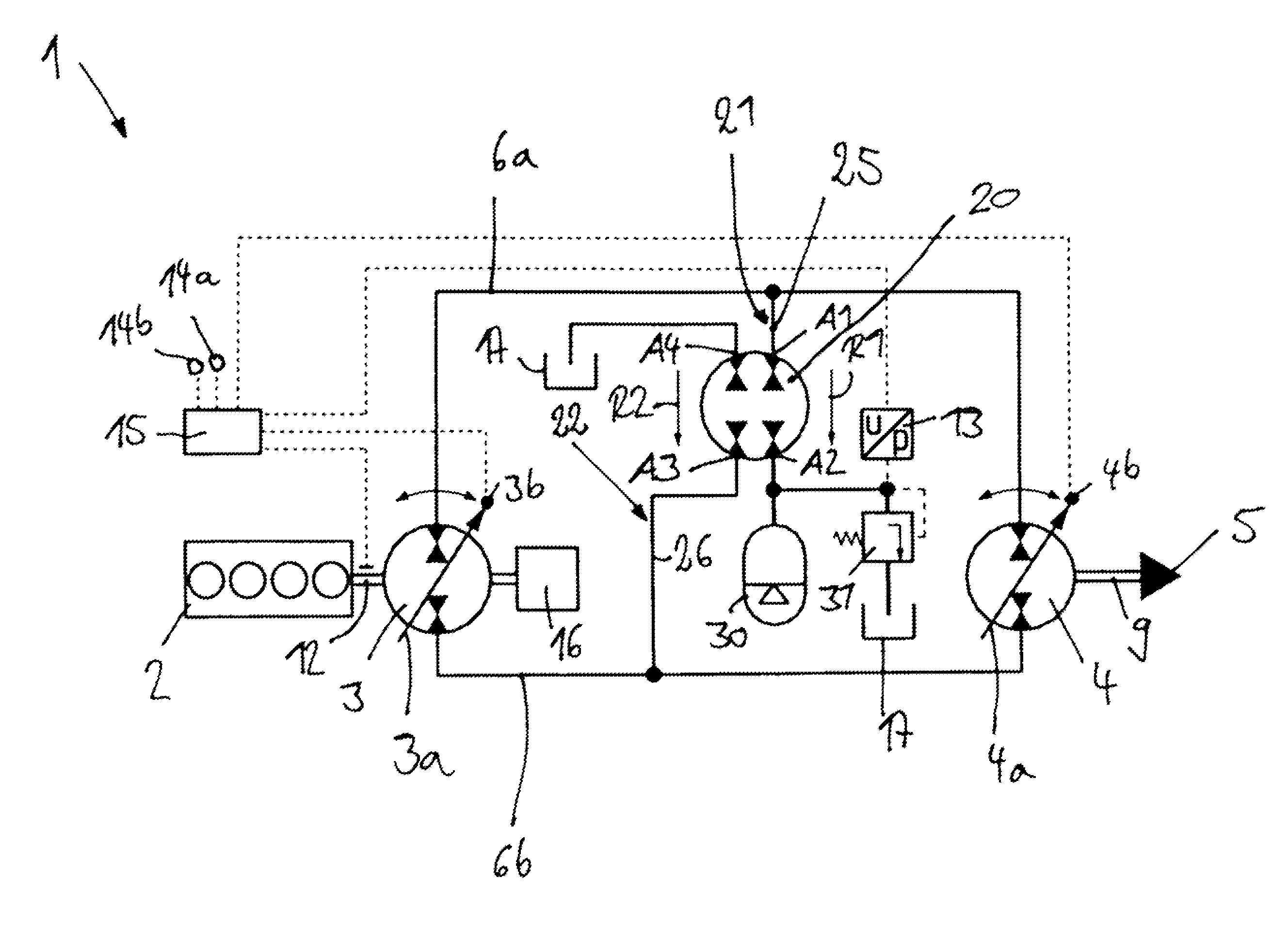
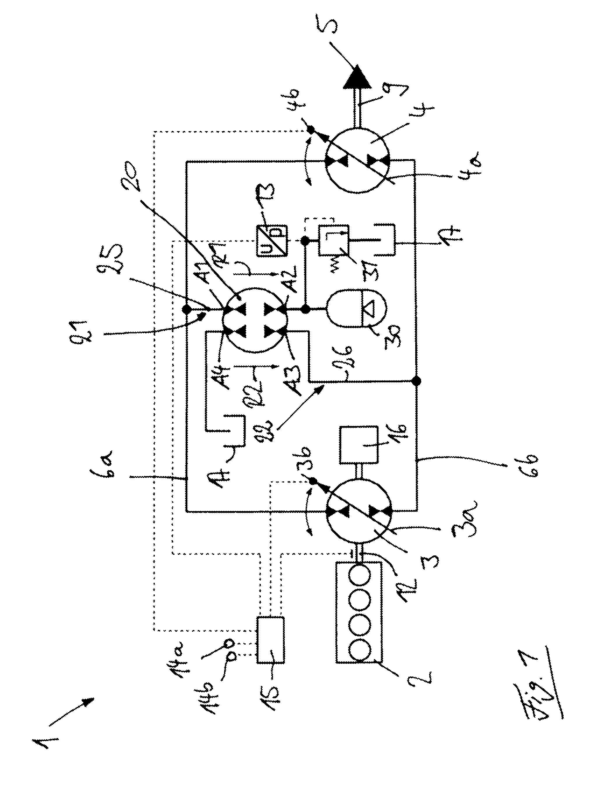
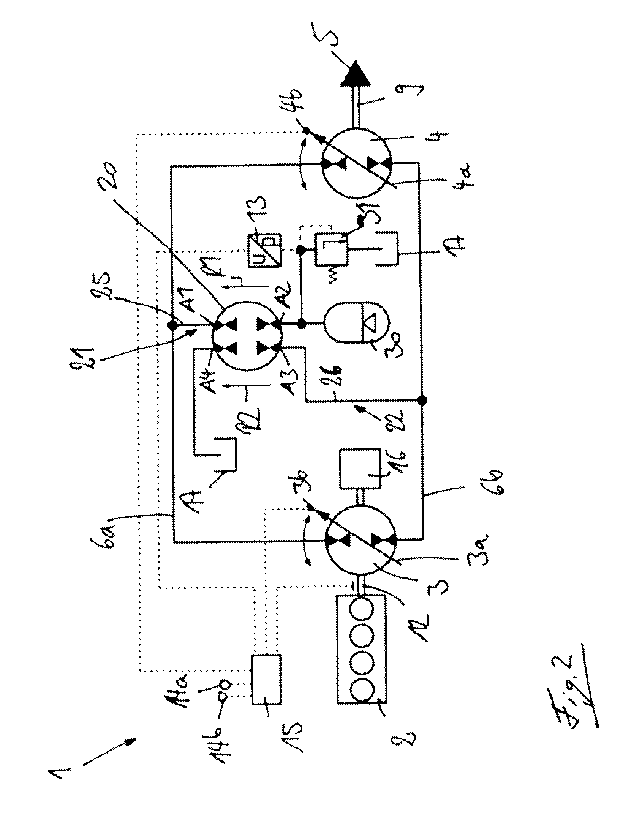
[0067]FIGS. 1 and 2 show a drive train of a vehicle with a hydrostatic drive system 1 of the invention.

[0068]The hydrostatic drive 1 has a hydrostatic pump 3 which is driven by a drive motor 2 and is connected in a closed circuit with a hydrostatic motor 4. The motor 4 is in a drive connection with a consumer 5. The closed circuit is formed by a first hydraulic connection 6a and a second hydraulic connection 6b.

[0069]In the illustrated exemplary embodiment the drive motor 4 is an internal combustion engine.

[0070]In the illustrated exemplary embodiment (e.g. FIG. 3), the consumer 5 is a traction drive system of a vehicle and comprises a drive axle 7 with two driven wheels 8a, 8b. An output shaft 9 of the motor 4 is in communication with a differential transmission 10 of the drive axle 7, which drives the wheels 8a, 8b by means of corresponding output shafts. The drive axle 7 can be driven directly by the motor 4. In the illustrated exemplary embodiment, the motor 4 is in a drive con...


PUM


Abstract

A hydrostatic drive system (1) has a hydrostatic pump (3) driven by a drive motor (2) and connected in a closed circuit with a hydrostatic motor (4). The hydrostatic motor (4) drives a consumer (5) and the closed circuit is formed by a first hydraulic connection (6a) and a second hydraulic connection (6b). A hydrostatic accumulator (30) can be connected with at least one of the two hydraulic connections (6a, 6b). A hydrostatic drive unit is located in an accumulator flow path (21) between one of the two hydraulic connections (6a, 6b) and the hydrostatic accumulator (30) and an additional hydrostatic drive unit is located in a tank flow path (22) between the other of the two hydraulic connections (6a, 6b) and a tank (17). The hydrostatic drive unit and the additional hydrostatic drive unit are a hydrostatic dual-flow double drive unit (20) provided in the accumulator flow path (21) and in the tank flow path (22).

Description

CROSS REFERENCE TO RELATED APPLICATIONS[0001]This application claims priority to German Application No. DE 102013114038.6 filed Dec. 13, 2013, which is herein incorporated by reference in its entirety.BACKGROUND OF THE INVENTION[0002]1. Field of the Invention[0003]This invention relates to a hydrostatic drive system with a hydrostatic pump which is driven by a drive motor and is connected in a closed circuit with a hydrostatic motor. The hydrostatic motor is in a drive connection with a consumer. The closed circuit is formed by a first hydraulic connection and a second hydraulic connection. A hydrostatic accumulator device can be connected with at least one of the two hydraulic connections for the storage of energy and the discharge of energy. A hydrostatic drive unit is located in an accumulator flow path between one of the two hydraulic connections and the hydrostatic accumulator and an additional hydrostatic drive unit is located in a tank flow path between the other of the two h...

Claims


Application Information

Patent Timeline
IPC IPC(8): F15B1/027F15B15/18F16H61/4096F15B1/02
CPCF15B1/027F15B1/024F15B2201/411F16H61/4096F15B15/18B60K6/12B60K2006/126F16H39/10F16H61/44F16H61/4139F16H61/42Y02T10/62F15B2211/214
Inventor KRITTIAN, LUKAS
Owner LINDE HYDRAULICS
Why Eureka
Try Eureka