Crank-drive with bearings having micro -ramp structures of asymmetric form

a technology of micro-ramps and bearings, which is applied in the direction of bearings, sliding contact bearings, shafts, etc., can solve the problems of bearing surface ramps, and achieve the effect of increasing the fluid pressure inside the micro-ramp and reducing the number of reynolds

Inactive Publication Date: 2015-07-23
THYSSENKRUPP METALURGICA CAMPO LIMPO
View PDF2 Cites 4 Cited by
  • Summary
  • Abstract
  • Description
  • Claims
  • Application Information

AI Technical Summary

Benefits of technology

[0015]The wedge-effect on the micro-ramp is described by the fluid passage inside the micro-ramp. In each micro-ramp, there is a gradual reduction of volume between the second concave section and the subsequent bearing surface. The gradual reduction of volume occurs between the maximum depth of the micro-ramp and the main or basic diameter of the journal and / or the housing. The fluid is restricted to flow from the second concave section to the subsequent bearing surface, dragging a constant quantity of fluid from a bigger to a smaller volume region, increasing the fluid pressure inside the micro-ramp.
[0016]In the region formed by the subsequent bearing surface is generated a hydrodynamic stabilization, reducing the Reynolds number and conditioning the fluid for the entrance in the next micro-ramp.
[0017]According to another embodiment of the inventive micro-ramp structure the bottom point features a depth below the bearing surface with an amount which is at least 50 times, preferably 100 times, more preferably 200 times and most preferred about 500 to 1000 times smaller than the total length of the first and second concave sections. This aspect ratio between the total length of the entire micro-ramp and the depth of the micro-ramp leads to a very flat shape of the structure, and in the groove formed by the micro-ramp a huge aggregation of lubricant is avoided and bubbles in the lubricant do not appear.

Problems solved by technology

The hydrodynamic bearing herein disclosed is performed for special high speed applications and do not allow low rotating speeds and are optimized for about 40.000 rpm.
Thus, a bearing having ramps in the bearing surface as herein disclosed are not applicable for crank-drive and in particular for supporting a crank-shaft in a crank-housing, because the bearing is not performed to provide a sufficient mechanical load.

Method used


Image

  • Crank-drive with bearings having micro -ramp structures of asymmetric form
  • Crank-drive with bearings having micro -ramp structures of asymmetric form
  • Crank-drive with bearings having micro -ramp structures of asymmetric form

Examples


Embodiment Construction

[0024]Additional details, characteristics and advantages of the invention are disclosed in the subclaims. The figures and the following description show preferred embodiments in an exemplary fashion of the subject matter according to the invention in conjunction with the accompanying figures, in which

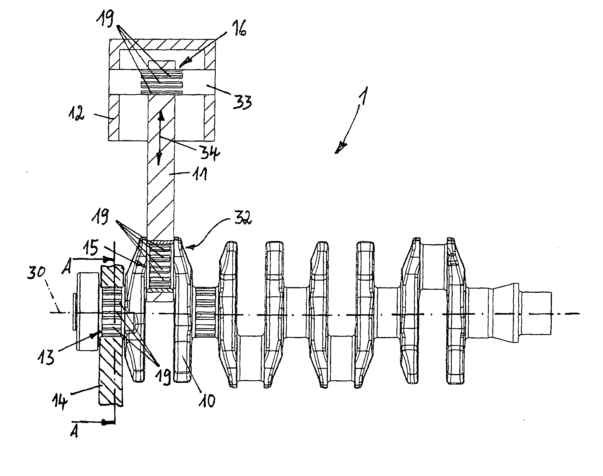
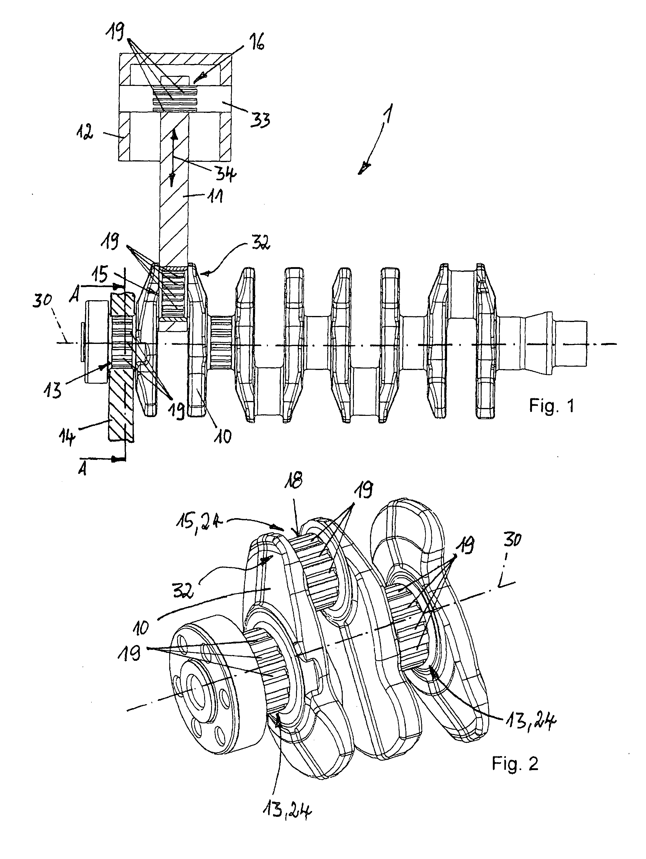
[0025]FIG. 1 shows an embodiment of a crank-drive with a crank-shaft, a connecting rod and a piston,

[0026]FIG. 2 shows a perspective view of a section of a crank-drive,

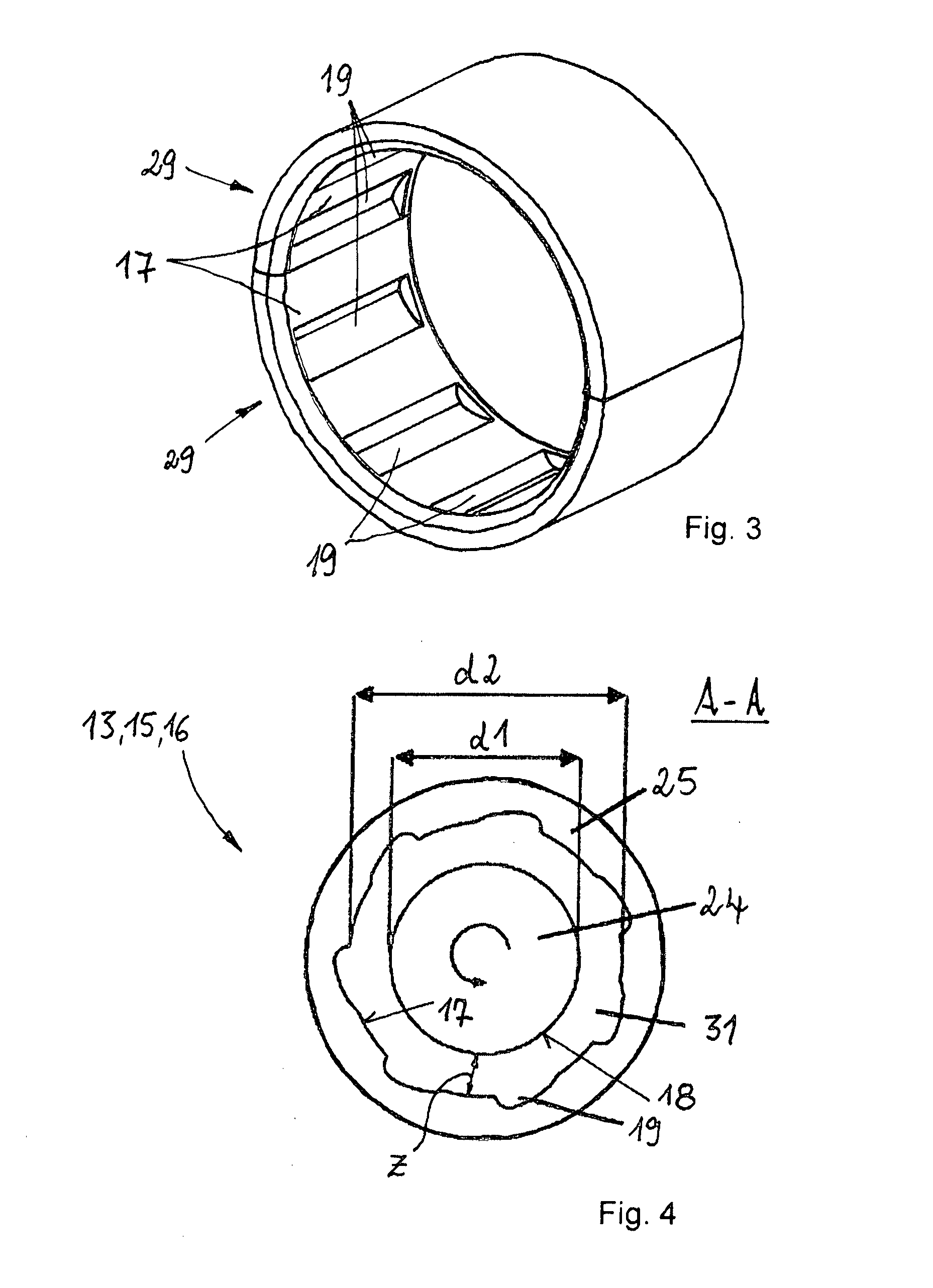
[0027]FIG. 3 shows a perspective view of a bearing element forming an baring insert,

[0028]FIG. 4 shows a cross section of a bearing with an inner and an outer bearing partner,

[0029]FIG. 5 shows a detailed view of a micro-ramp structure and an opposite bearing partner and

[0030]FIG. 6 shows a detailed view of a micro-ramp structure in an uncoiled extended section of a bearing partner.

[0031]FIG. 1 shows an embodiment of a crank-drive 1 with a crank-shaft 10, a connecting rod 11 and a piston 12, whereas the connecting rod 11 ...


PUM


Abstract

The present invention relates to a crank-drive with a crank-shaft, at least one connecting rod and at least one piston, in particular a crank-drive of an internal combustion engine, whereas the crank-shaft features at least one radial bearing (13) for supporting the crank-shaft in a crank-housing, at least one radial bearing for connecting the connecting rod to the crank-shaft, and the connection of the connecting rod to the piston features at least one radial bearing and whereas the bearings feature a bearing inner surface and/or a bearing outer surface. According to the invention in at least one of the bearing surfaces are arranged micro-ramp structures with an asymmetric form having a first concave section between the bearing surface and a bottom point of the micro-ramp structure and a second concave section between the bottom point and the bearing surface, whereas between the micro-ramp structures are arranged sections of the bearing surface.

Description

[0001]The present invention relates to a crank-drive with a crank-shaft, at least one connecting rod and at least one piston, in particular a crank-drive of an internal combustion engine, whereas the crank-shaft features at least one radial bearing for supporting the crank-shaft in a crank-housing, at least one radial bearing for connecting the connecting rod to the crank-shaft, and the connection of the connecting rod to the piston features at least one radial bearing and whereas the bearings feature a bearing inner surface and / or a bearing outer surface. Moreover the present invention is directed to a crank-shaft of a crank-drive, a radial bearing for such a crank-drive and a radial bearing itself.[0002]In the last few decades a lot of research has been done in the field of plain bearings in general. Most of the investigations have been done in the field called “micro grooves” or “micro ramps” in at least one of the surfaces of the radial bearing partners. It consists of inserting...

Claims


Application Information

Patent Timeline
Patent Type & Authority Applications(United States)
IPC IPC(8): F16C9/02F16C9/04
CPCF16C9/04F16C9/02F16C17/028F16C2240/40F16C2240/44
Inventor BARBOSA DE OLIVEIRA FERREIRA SALLES, BRUNOSANTORO CARDOSO, RICARDODUARTE, DURVAL
Owner THYSSENKRUPP METALURGICA CAMPO LIMPO
Why Eureka
Try Eureka