Well Test Burner System and Method

a burner and burner technology, applied in the direction of combustion types, lighting and heating apparatus, incinerator apparatus, etc., can solve the problems of increasing the cost of performing the testing operation, raising environmental and safety concerns, and new technological challenges, so as to reduce the biasing force, and minimize the fallout of unburned waste effluent

Inactive Publication Date: 2015-07-23
SCHLUMBERGER TECH CORP
View PDF14 Cites 5 Cited by
  • Summary
  • Abstract
  • Description
  • Claims
  • Application Information

AI Technical Summary

Benefits of technology

[0005]Systems and methods are disclosed herein for combusting fluids having a hydrocarbon content. The fluids may be generated during well testing, oil spill cleanup, or other operations. According to the systems and methods disclosed herein, flow control elements used to control waste effluent flow to burner nozzles are biased to a closed position by a biasing force. Reduced biasing forces are applied to selected flow control elements so that the burner nozzles associated with the selected flow control elements will open first during startup and close last during shut down. The flow control elements receiving reduced biasing forces may be selected according to proximity of the associated burner nozzles to one or more pilots so that combustion occurs more reliably and fallout of unburned waste effluent is minimized.

Problems solved by technology

As relatively accessible hydrocarbon deposits are depleted, hydrocarbon prospecting and production has expanded to new regions that may be more difficult to reach and / or may pose new technological challenges.
The costs associated with performing the testing operations may be significant, however, and therefore testing operations should be performed as efficiently and economically as possible.
Fluids produced from the test well are generally considered to be waste and therefore are typically disposed of by burning, which raises environmental and safety concerns.

Method used


Image

  • Well Test Burner System and Method
  • Well Test Burner System and Method
  • Well Test Burner System and Method

Examples


Embodiment Construction

[0016]So that the above features and advantages of the present disclosure can be understood in detail, a more particular description of the disclosure, briefly summarized above, may be had by reference to the embodiments thereof that are illustrated in the accompanying drawings. It is to be noted, however, that the drawings illustrate only typical embodiments of this disclosure and therefore are not to be considered limiting of its scope, for the disclosure may admit to other equally effective embodiments.

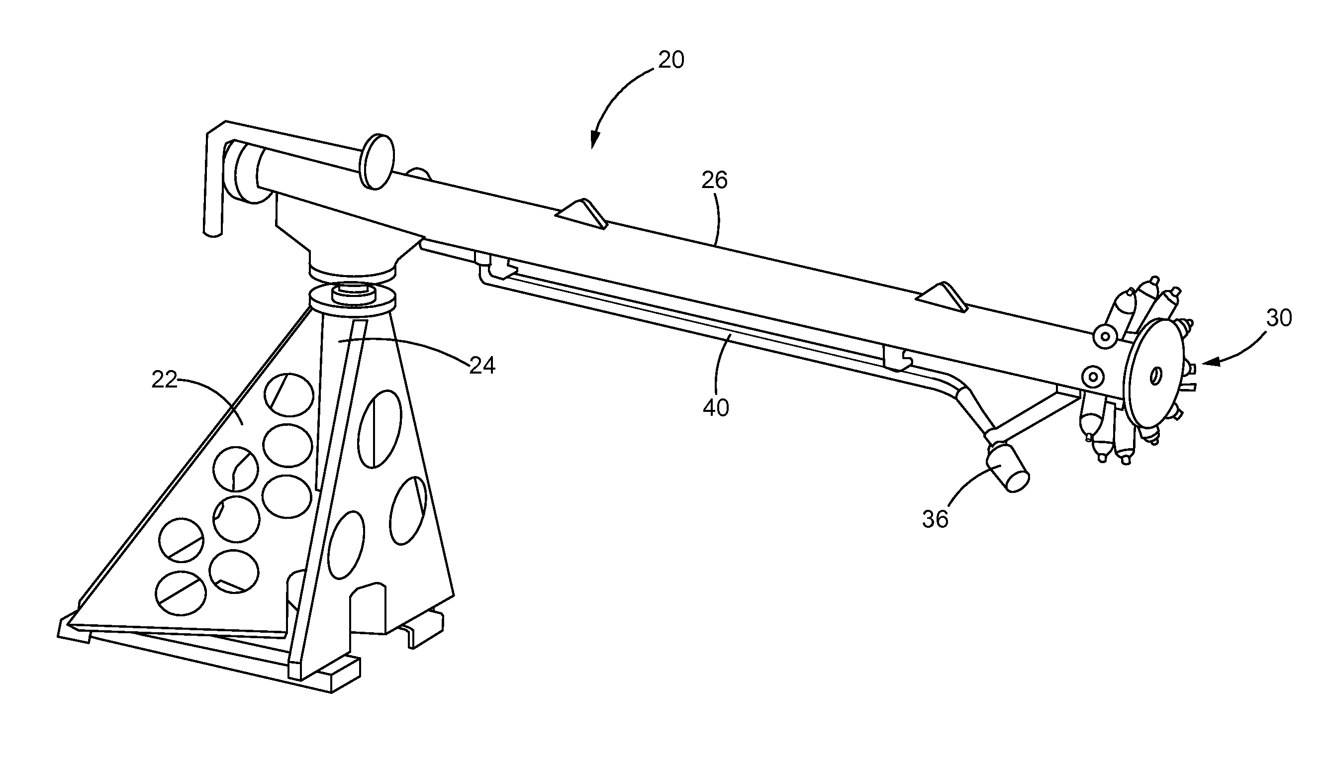
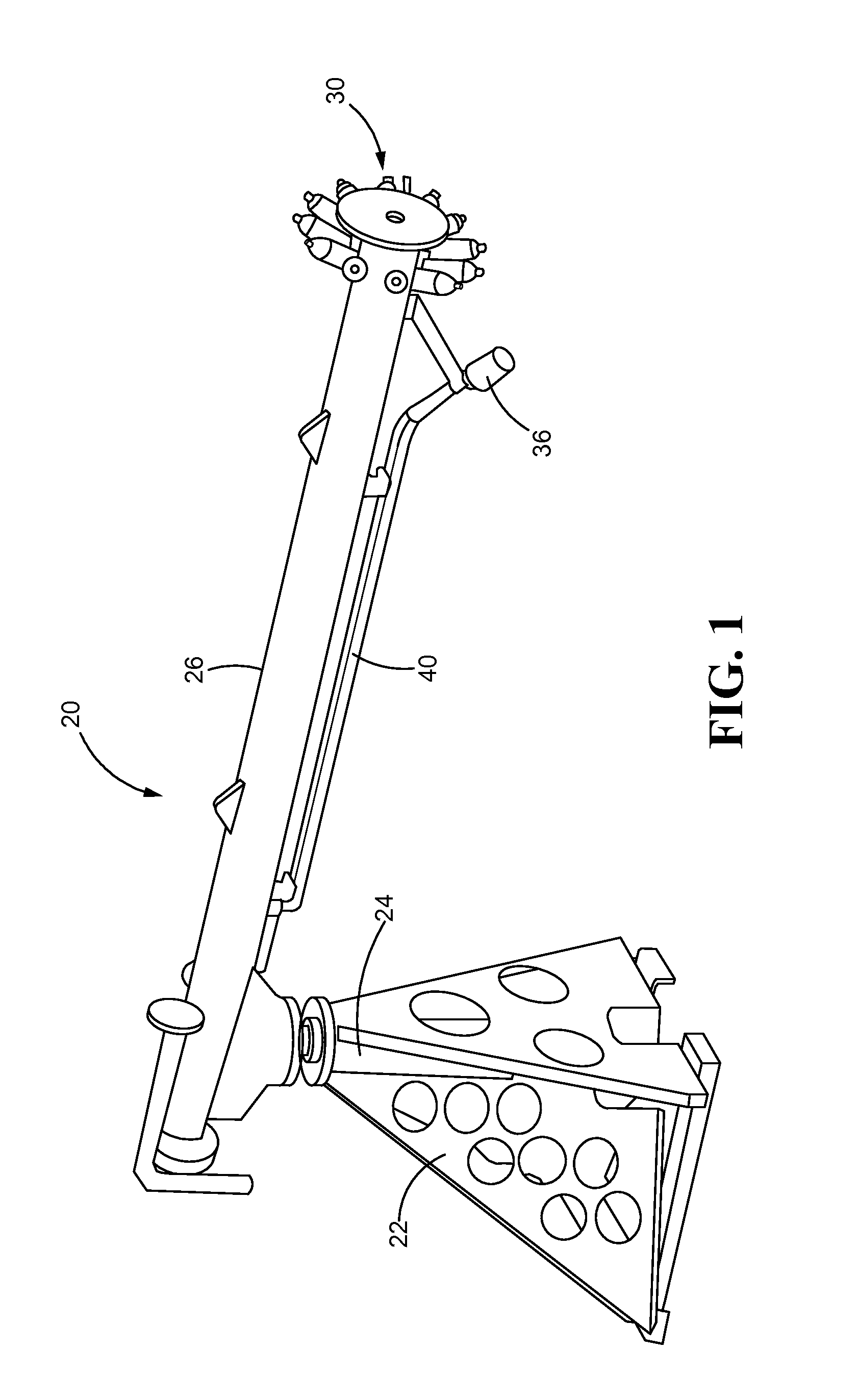
[0017]Methods and apparatus are disclosed herein for combusting waste effluent generated by well testing, oil spill cleanup, or other operations. The term “waste effluent” is intended to encompass any fluid having a hydrocarbon content capable of being disposed of by combustion. The waste effluent may include a liquid hydrocarbon content (such as oil), a gas hydrocarbon content (such as methane), and non-hydrocarbon containing content (such as seawater). The waste effluent may be o...


PUM


Abstract

Methods and systems of burning waste effluent include controlling flow of waste effluent to burner nozzles using flow control elements. The flow control elements are biased toward closed positions using biasing forces, wherein reduced biasing forces are applied to selected flow control elements so that waste effluent flow first reaches the burner nozzles associated with the flow control elements receiving reduced biasing forces. The selected burner nozzles may be located nearer a pilot to more reliably induce combustion and reduce fallout.

Description

BACKGROUND OF THE DISCLOSURE[0001]Hydrocarbons are widely used as a primary source of energy, and have a significant impact on the world economy. Consequently, the discovery and efficient production of hydrocarbon resources is increasingly important. As relatively accessible hydrocarbon deposits are depleted, hydrocarbon prospecting and production has expanded to new regions that may be more difficult to reach and / or may pose new technological challenges. During typical operations, a borehole is drilled into the earth, whether on land or below the sea, to reach a reservoir containing hydrocarbons. Such hydrocarbons are typically in the form of oil, gas, or mixtures thereof which may then be brought to the surface through the borehole.[0002]Well testing is often performed to help evaluate the possible production value of a reservoir. During well testing, a test well is drilled to produce a test flow of fluid from the reservoir. During the test flow, key parameters such as fluid press...

Claims


Application Information

Patent Timeline
Patent Type & Authority Applications(United States)
IPC IPC(8): F23G7/06F23Q9/00F23D99/00F23G7/05
CPCF23G7/06F23D21/00F23Q9/00F23G7/05F23G7/08F23C6/047F23D14/045
Inventor TOLSTOUKHOV, ALEKSEY
Owner SCHLUMBERGER TECH CORP
Why Eureka
Try Eureka