Frozen evaporator coil detection and defrost initiation

a technology of evaporator coil and evaporator coil, which is applied in the direction of defrosting, domestic cooling apparatus, lighting and heating apparatus, etc., can solve the problems of reducing the cooling capacity degrading the heat transfer performance of the evaporator coil, and affecting the operation of the refrigeration system

Active Publication Date: 2015-07-23
CARRIER CORP
View PDF5 Cites 24 Cited by
  • Summary
  • Abstract
  • Description
  • Claims
  • Application Information

AI Technical Summary

Problems solved by technology

Refrigerant vapor compression systems used in connection with transport refrigeration systems are generally subject to stringent operating conditions due to the wide range of operating load conditions and the wide range of outdoor ambient conditions over which the refrigerant vapor compression system must operate to maintain product within the cargo space at a desired temperature.
Additionally, the build-up of ice on the exposed heat transfer surfaces of the evaporator coil creates additional thermal resistance to the transfer of heat from the air flow to the refrigerant passing through the heat exchange tubes of the evaporator coil, thereby degrading the heat transfer performance of the evaporator coil and lowering the cooling capacity of the evaporator coil.
However, as a cooling demand is still imposed on the system, the system will cycle back on.
An undesirable on-off cycling of the compressor may ensue.

Method used


Image

  • Frozen evaporator coil detection and defrost initiation
  • Frozen evaporator coil detection and defrost initiation
  • Frozen evaporator coil detection and defrost initiation

Examples


Embodiment Construction

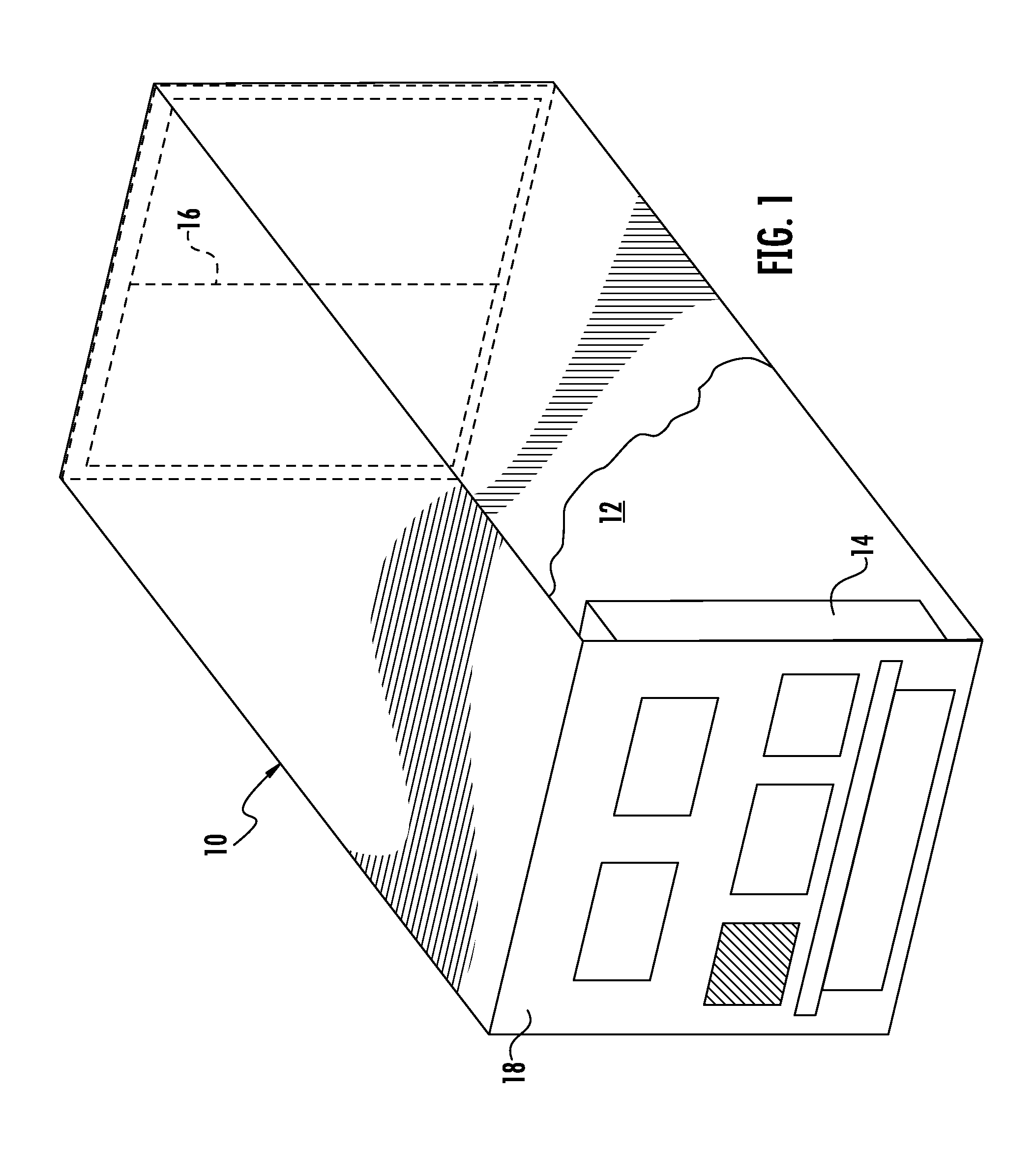
[0016]There is depicted in FIG. 1 an exemplary embodiment of a refrigerated container 10 having a temperature controlled cargo space 12 the atmosphere of which is refrigerated by operation of a transport refrigeration unit 14 associated with the cargo space 12. In the depicted embodiment of the refrigerated container 10, the transport refrigeration unit 14 is mounted in an opening in the front wall of the refrigerated container 10 as in conventional practice. However, the refrigeration unit 14 may be mounted in or on the roof, floor or any wall of the refrigerated container 10. Additionally, the refrigerated container 10 has at least one access door 16 through which perishable products and goods, fresh or frozen, may be loaded into and removed from the cargo space 12 of the refrigerated container 10.

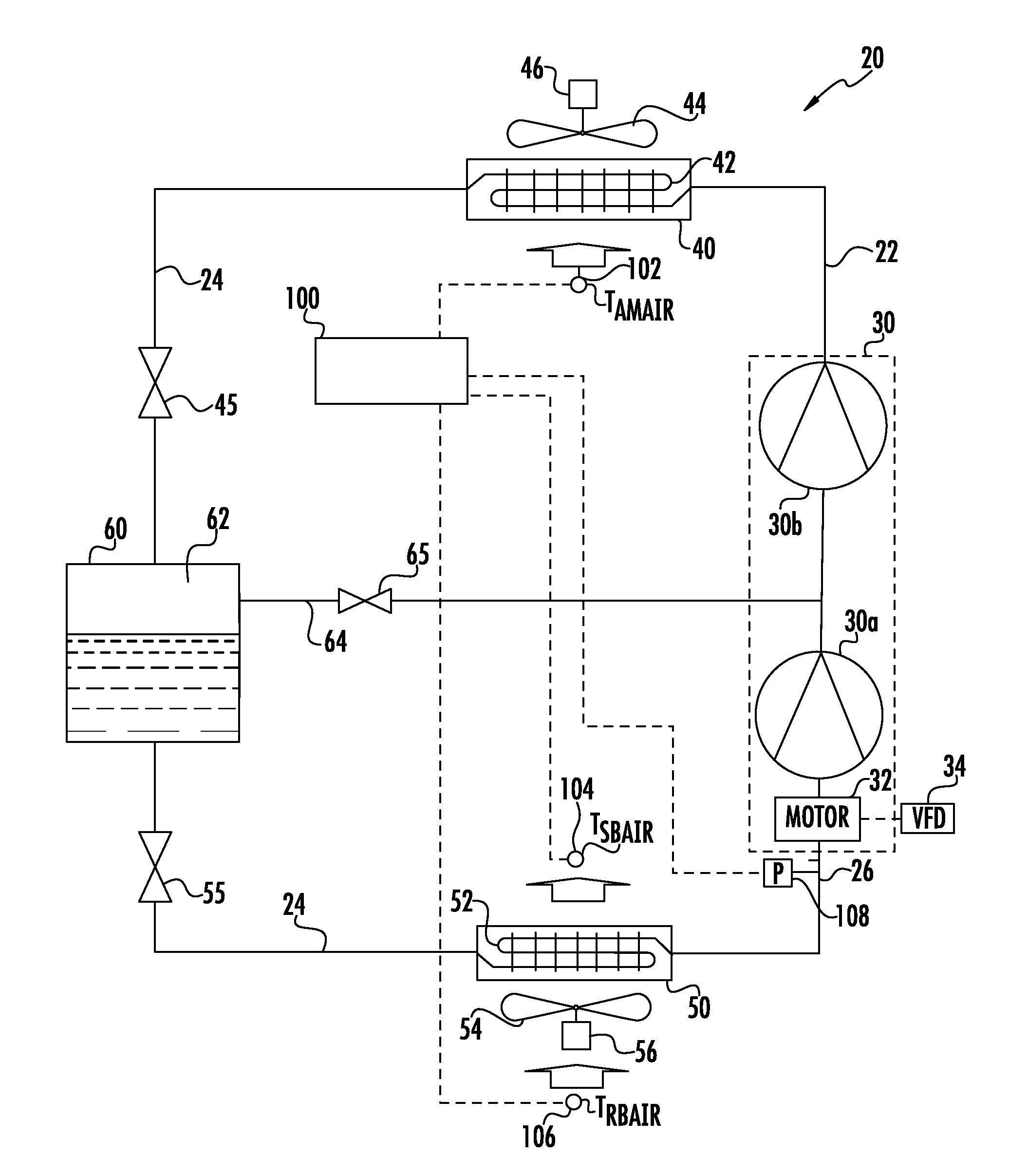
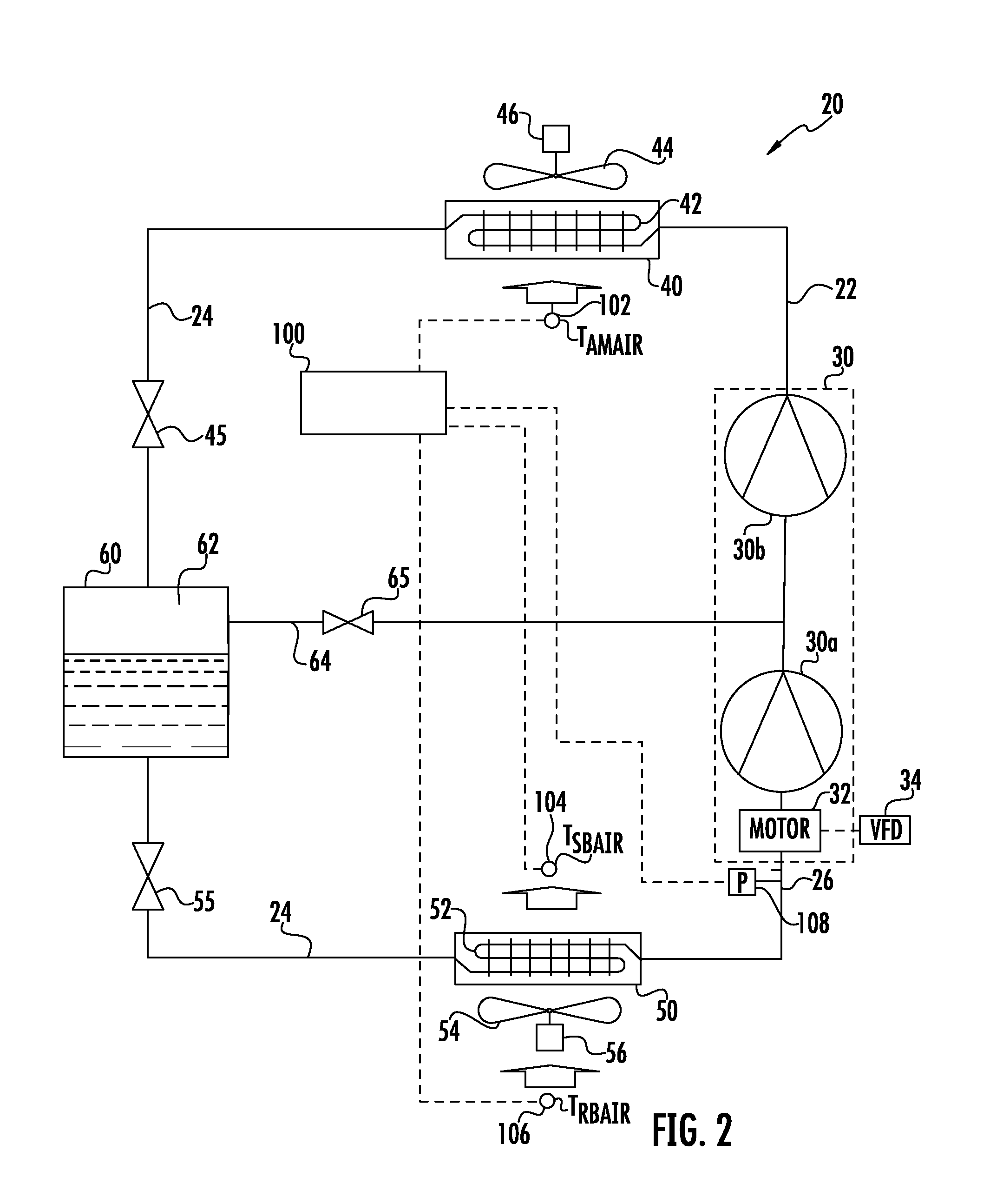
[0017]The transport refrigeration unit 14 includes a refrigerant vapor compression system 20 for refrigerating air drawn from and supplied back to the temperature controlled space 12. Re...


PUM


Abstract

A method is disclosed or detecting a frozen evaporator coil of a refrigerant vapor compression system for supplying conditioned air to a temperature controlled space before ice build-up on the evaporator coil becomes so excessive as to result in an undesirable on-off cycling of the refrigerant vapor compression system compressor when operating to a frozen temperature maintenance mode. The method may also include initiating a defrost of a frozen evaporator coil of the refrigerant vapor compression system before ice build-up on the evaporator coil becomes so excessive as to result in an on-off cycling of the refrigerant vapor compression system compressor when operating to a frozen temperature maintenance mode.

Description

BACKGROUND OF THE DISCLOSURE[0001]This disclosure relates generally to refrigerant vapor compression systems and, more particularly, to detecting and defrosting the heat exchanger coil of an evaporator of a refrigerant vapor compression system when supplying cold air to a temperature controlled space being maintained at a temperature below the freezing point of water (32° F. / 0° C.).[0002]Refrigerant vapor compression systems used in connection with transport refrigeration systems are generally subject to stringent operating conditions due to the wide range of operating load conditions and the wide range of outdoor ambient conditions over which the refrigerant vapor compression system must operate to maintain product within the cargo space at a desired temperature. The desired temperature at which the cargo needs to be controlled can also vary over a wide range depending on the nature of cargo to be preserved. For example, for fresh products, such as produce, dairy products, fresh me...

Claims


Application Information

Patent Timeline
Patent Type & Authority Applications(United States)
IPC IPC(8): F25B47/02
CPCF25B47/02F25B1/10F25B41/20F25B2347/023F25B2400/13F25B2700/1933F25B2700/21161F25B2700/21171
Inventor LIU, LUCY YI
Owner CARRIER CORP
Why Eureka
Try Eureka