
Network manageable advanced gas sensor apparatus and method

a gas sensor and network management technology, applied in the field of intelligent gas sensors, can solve the problems of arc suppression safety, no fully integrated, economical, network interface-able component for automatically monitoring sfsub>6 /sub>gas trends, and high equipment and labor costs of ir imaging approaches such as epri and flir devices, and achieve the effect of easy integration

Active Publication Date: 2015-07-23
MODTECH
View PDF12 Cites 17 Cited by
  • Summary
  • Abstract
  • Description
  • Claims
  • Application Information

AI Technical Summary

Benefits of technology

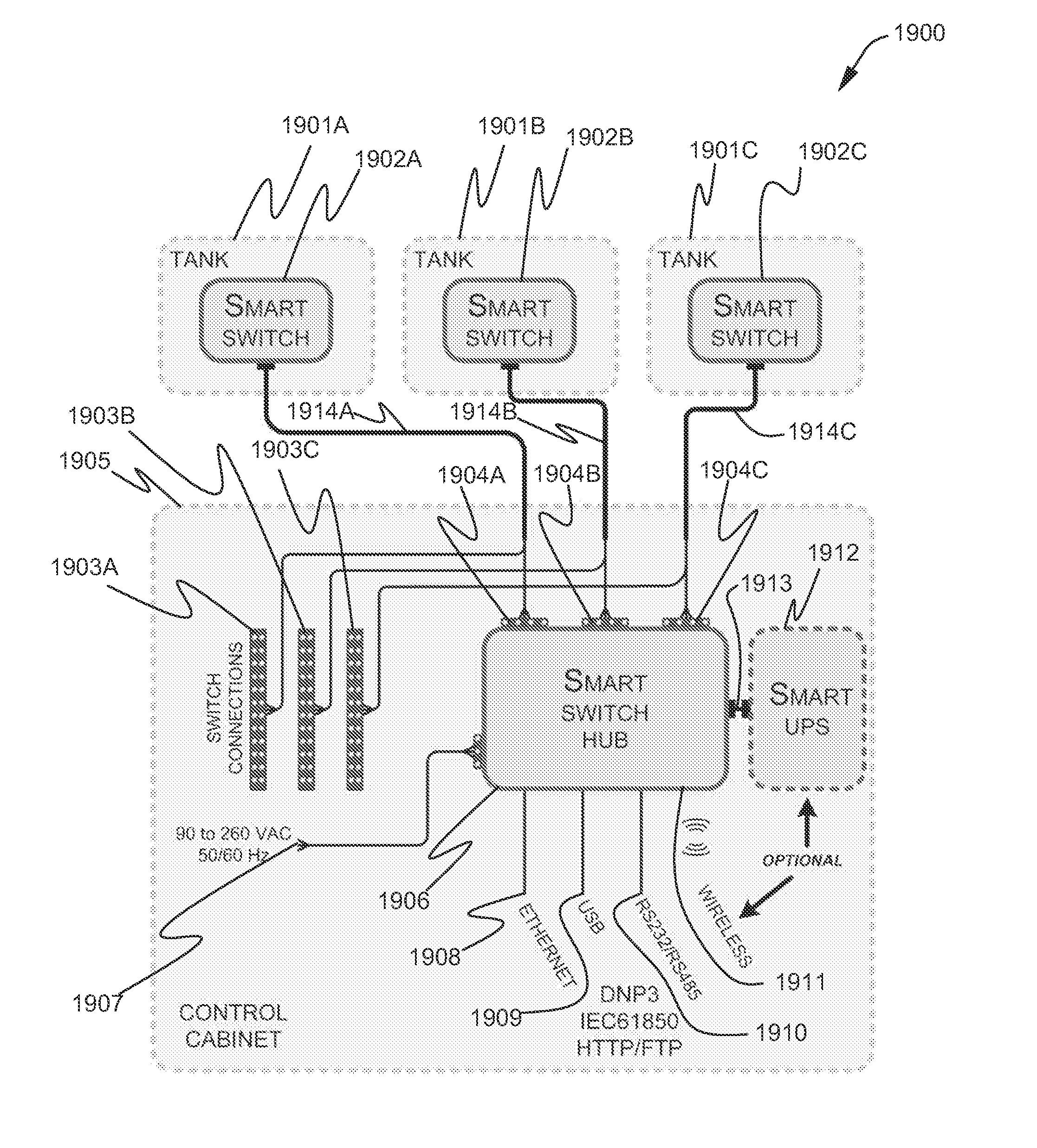
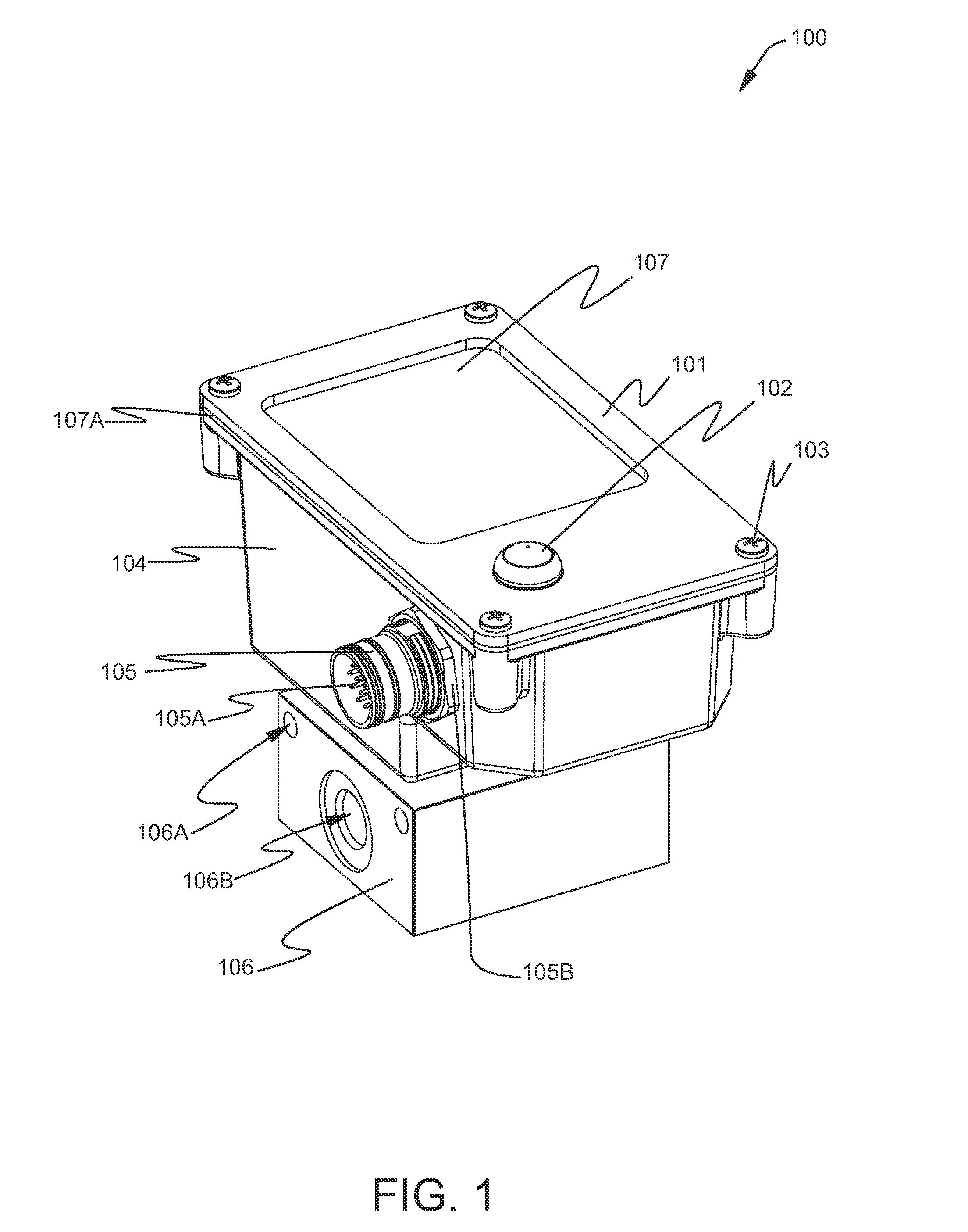
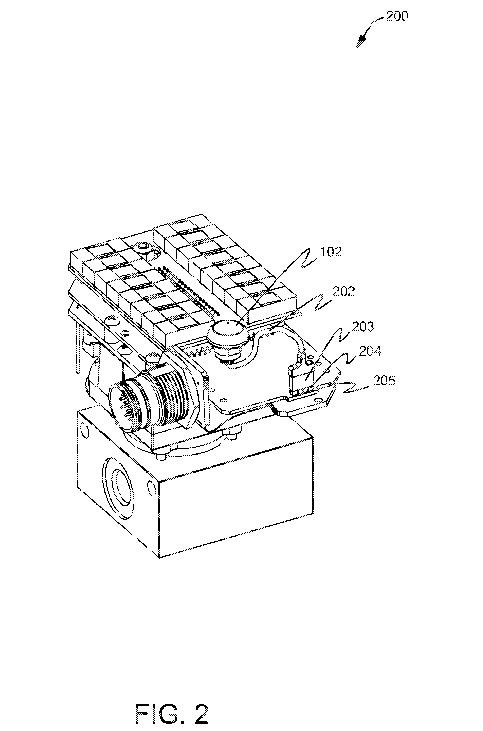
This invention is a technology platform for highly integrated gas sensors that can detect and mitigate atmospheric pollution caused by leaking SF6. These sensors can be integrated into gas insulated tank of breakers and switch units, with millions of sensors expected to be used in the world's electricity infrastructure. The sensors use advanced mechanical, electronic, algorithmic, and network facets to accurately monitor changes in gas content in real-time. They can detect and log repair events and will be able to close the overall monitoring and mitigation loop. The technology is easy to integrate into existing network management infrastructure and is cost-effective for electric utilities and manufacturers of gas density switches. The invention supports flexible optioning and extends functionality, making it ideal for the surgical detection, tracking, and mitigation of SF6 loss through equipment leakage. The economic benefits of this invention are manifold.

Problems solved by technology

Although a variety of devices and systems for monitoring and measuring aspects of SF6 gas in laboratory and field settings are currently described in the research and trade literature, none represent a fully integrated, economical, network interface-able component for automatically monitoring SF6 gas trends in real-time on a tank-by-tank globally distributed basis.
Approaches based upon IR imaging such as EPRI and FLIR devices are expensive in both equipment and labor and therefore find use monitoring for gas leaks only on a spot versus continuous basis.
Arc-suppression safety becomes an issue when gas supply is insufficient.
Overpressure is problematic with excess gas levels.

Method used


Image

  • Network manageable advanced gas sensor apparatus and method
  • Network manageable advanced gas sensor apparatus and method
  • Network manageable advanced gas sensor apparatus and method

Examples


Embodiment Construction

[0089]As stated above, the instant invention supports a 100-fold reduction in gas emissions. What does this imply for gas density measurement requirements? To address this question, begin by considering that, at a temperature of 20° C., the operating pressure for the breakers of table 1 ranges from 64 psig to 82 psig, a span of 18 psi.

[0090]Table 1 also gives the nominal gas mass change attributable to pressure change for each breaker under the aforementioned isothermal conditions. The function is simply proportional to the differential tank volume of the various breakers given the isothermal assumption. As expected, the largest tank represents a worst case requirement for mass sensing resolution since smaller pressure changes accompany larger gas losses (large mass changes). In general, larger tanks will require higher resolution measurements to detect unit changes in gas mass.

TABLE 1Breaker Model DesignationHSHP-1HP-2HP-3HPI-1HPI-2Rated72.5145169242345550MaximumVoltage (kV)Interru...


PUM


Abstract

Mechanical, electronic, algorithmic, and computer network facets are combined to create a highly integrated advanced gas sensor system. The sensor system, utilized with gas insulated high voltage switchgear products, deployed by electric utility end users in replacement and expansion cycles, function to detect and mitigate atmospheric pollution caused by leaking SF6. As its associated gas insulated tank is charged with 10 to 350 lbs. of SF6, each gas sensor monitors its local cache of gas, accurately sensing and computing fractional percentage losses (emissions) and gains (maintenance replacement) in SF6 mass, storing data in onboard data logs, and communicating data when triggered by detection events or in response to remote requests over a hierarchical communications network, a process that continues without labor until a fractional leak is automatically detected and reported creating the opportunity for early leak mitigation.

Description

[0001]This application claims priority to copending: U.S. patent application Ser. No. 13 / 568,108 filed Aug. 6, 2012 and to U.S. Patent Application No. 61 / 699,835 filed Sep. 11, 2012.[0002]This application incorporates copending U.S. patent application Ser. No. 13 / 568,108 filed Aug. 6, 2012 by reference hereto in its entirety. This application incorporates copending U.S. Patent Application No. 61 / 699,835 filed Sep. 11, 2012 by reference hereto in its entirety.[0003]This application incorporates copending U.S. Provisional patent application Ser. No. 61 / 515,834 filed Aug. 5, 2011 by reference hereto in its entirety. This application incorporates copending U.S. Provisional patent application Ser. No. 61 / 542,261 filed Oct. 2, 2011 by reference hereto in its entirety.FIELD OF THE INVENTION[0004]The field of invention is the field of intelligent gas sensors with the capability to measure the pressure and temperature of one or more target gas substances contained in a known volume and to co...

Claims


Application Information

Patent Timeline
Patent Type & Authority Applications(United States)
IPC IPC(8): G01M3/26G01M3/00G05B15/02
CPCG01M3/26G01M3/002G05B15/02G01D5/142G01K7/22G01N9/266
Inventor SCHEUCHER, KARL FREDERICK
Owner MODTECH
Learn More