Vehicle installed battery pack with pressure release structure

a technology of pressure release structure and battery pack, which is applied in the direction of batteries, cell lids/covers, cell components, etc., can solve the problems of increased internal pressure of the case chamber, lack of function of the unit, etc., and achieve the effect of reducing joint strength and reducing joint strength

Active Publication Date: 2015-07-23
NISSAN MOTOR CO LTD
View PDF7 Cites 18 Cited by
  • Summary
  • Abstract
  • Description
  • Claims
  • Application Information

AI Technical Summary

Benefits of technology

[0012]In an area corresponding to the deforming stepped portion within the seal member extending continuously about the entire perimeter, there is established a weakly joined portion of lower joint strength than in the rest of the joined portion.
[0013]As described above, the battery pack upper cover is provided with a deforming stepped portion having a height difference at least in the heightwise direction. Then, in an area of the seal member which extends continuously about the entire perimeter, the area corresponding to the deforming stepped portion, there is established a weakly joined portion of lower joint strength than in the rest of the joined portion. Consequently, when gases are produced from the battery module arranged in the interior of the case chamber, and the internal pressure of the case chamber rises, the internal pressure concentrates in a section protruding furthest to the case center side within the case structure, specifically, the deforming stepped portion of the battery pack upper cover. Due to this internal pressure concentration, in the deforming stepped portion, the battery pack upper cover undergoes deformation in a direction that eliminates the height difference of the step in the heightwise direction, i.e., in the heightwise direction from the lower step to towards the higher step. Due to this deformation of the cover, the joint of the weakly joined portion which has been established in the area corresponding to the deforming stepped portion splits, the outside peripheral edge portion of the battery pack upper cover separates from the outside peripheral edge portion of the battery pack lower frame, and an opening forms in the weakly joined portion. For this reason, when internal pressure of the case chamber has risen due to production of gases, the internal gases are discharged to the outside from the opening of the weakly joined portion, without inducing rupture or breakage of the battery pack upper cover. Thus, internal pressure concentrated at the deforming stepped portion of the battery pack upper cover prompts deformation of the battery pack upper cover, and in association with deformation of the cover, the weakly joined portion splits, forming an opening through which the case chamber communicates with the outside air. For this reason, when internal pressure of the case chamber has risen due to production of gases, the internal gases can be discharged to the outside through the separable opening of the weakly joined portion.

Problems solved by technology

However, while the case chamber can be hermetically sealed in these conventional vehicle installed battery packs, a problem is presented in that the units lack a function whereby, when the internal pressure of the case chamber has risen due to production of gases, the internal gases are discharged to the outside.
Specifically, in the case of a vehicle installed battery pack, when an adverse event such as overcharging occurs, gases are produced from the battery module which is situated in the interior of the case chamber and which includes multiple battery cells, leading in some cases to increased internal pressure of the case chamber.

Method used


Image

  • Vehicle installed battery pack with pressure release structure
  • Vehicle installed battery pack with pressure release structure
  • Vehicle installed battery pack with pressure release structure

Examples


first embodiment

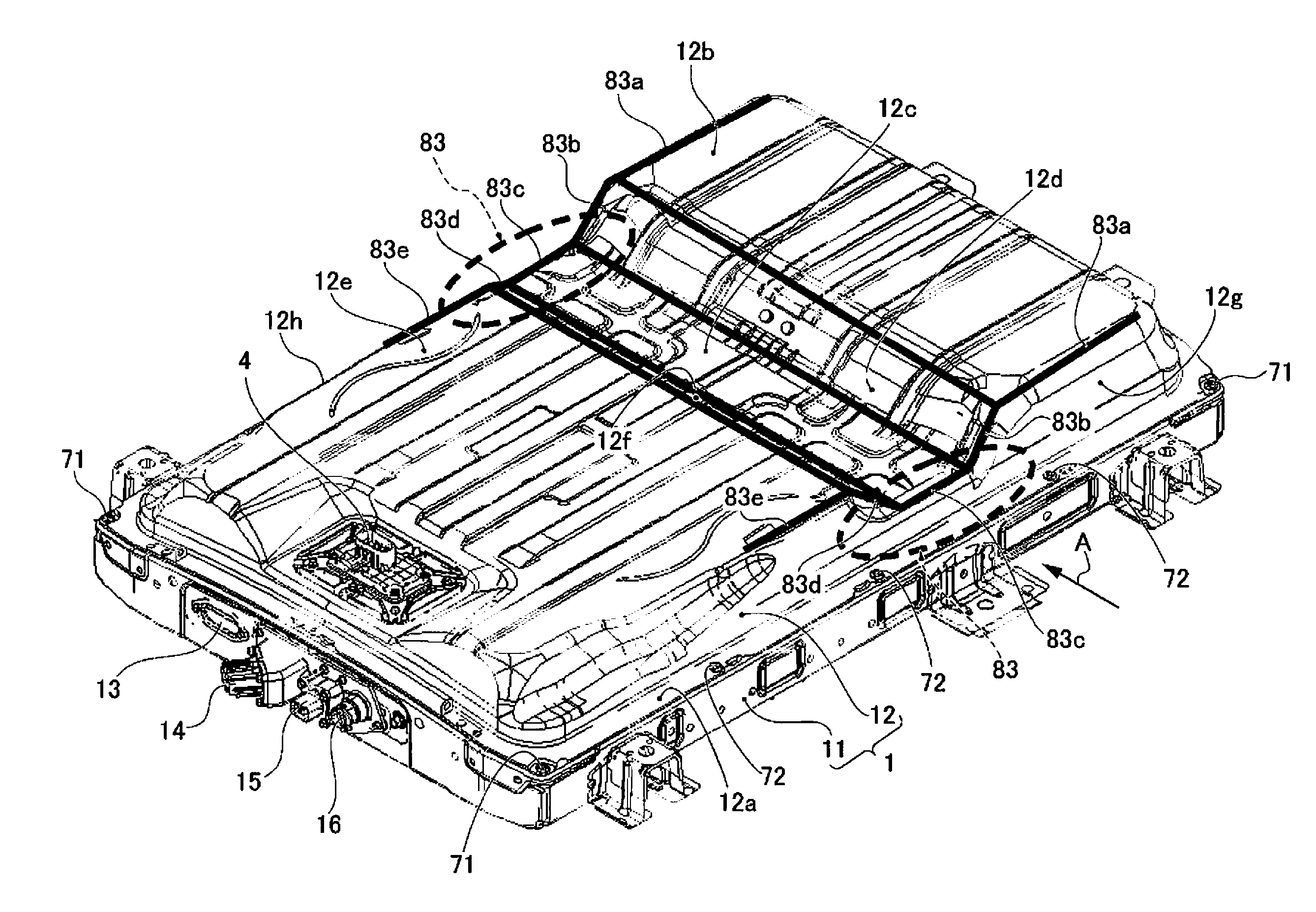
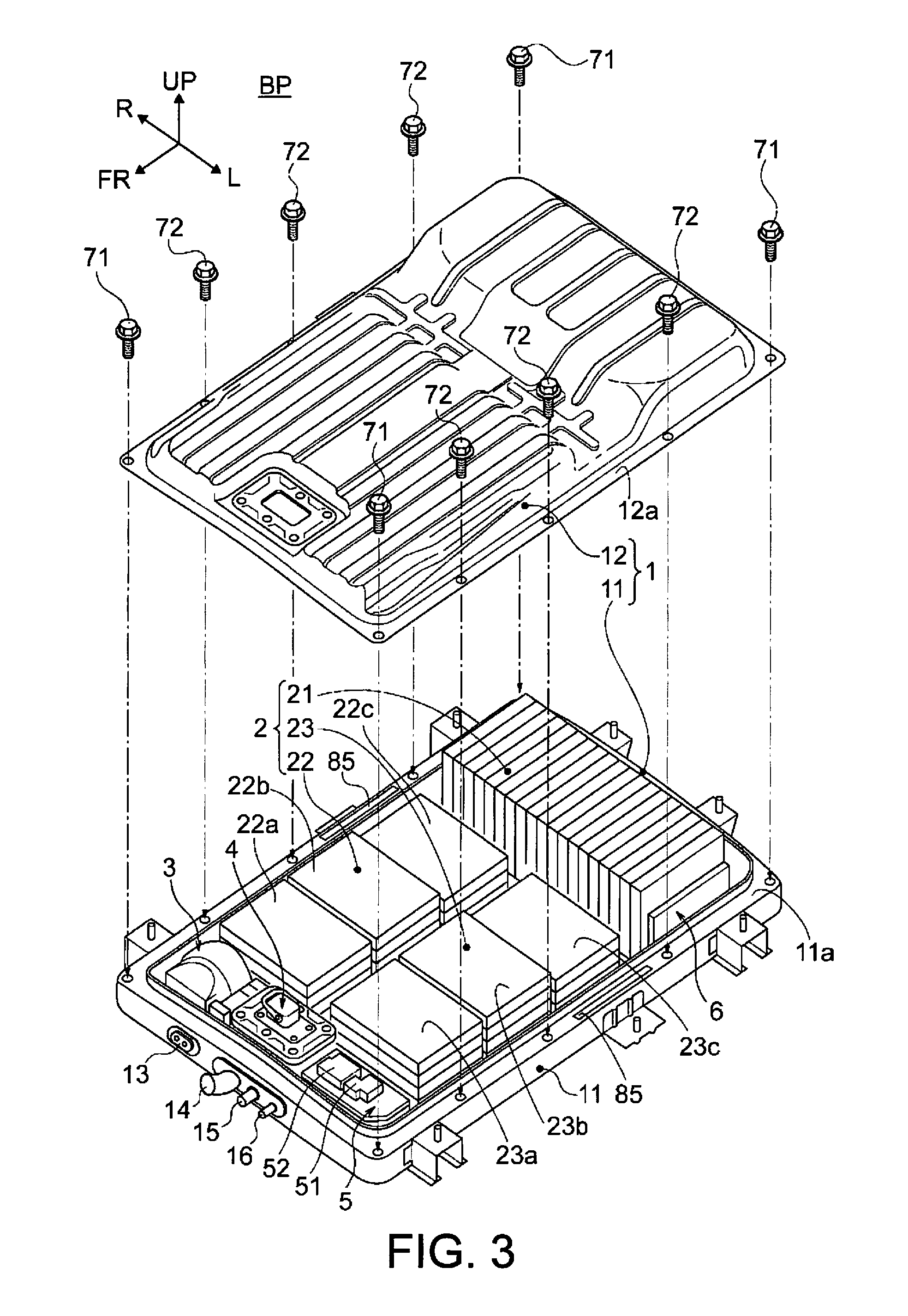
[0028]First, the configuration will be described. The description of the configuration in the pressure release structure for a vehicle installed battery pack of the first embodiment will be divided into the “Schematic configuration of electric car with battery pack installed,”“Configuration of battery pack,” and “Detailed configuration of pressure release structure provided to battery pack.”

Schematic Configuration of Electric Car with Battery Pack Installed

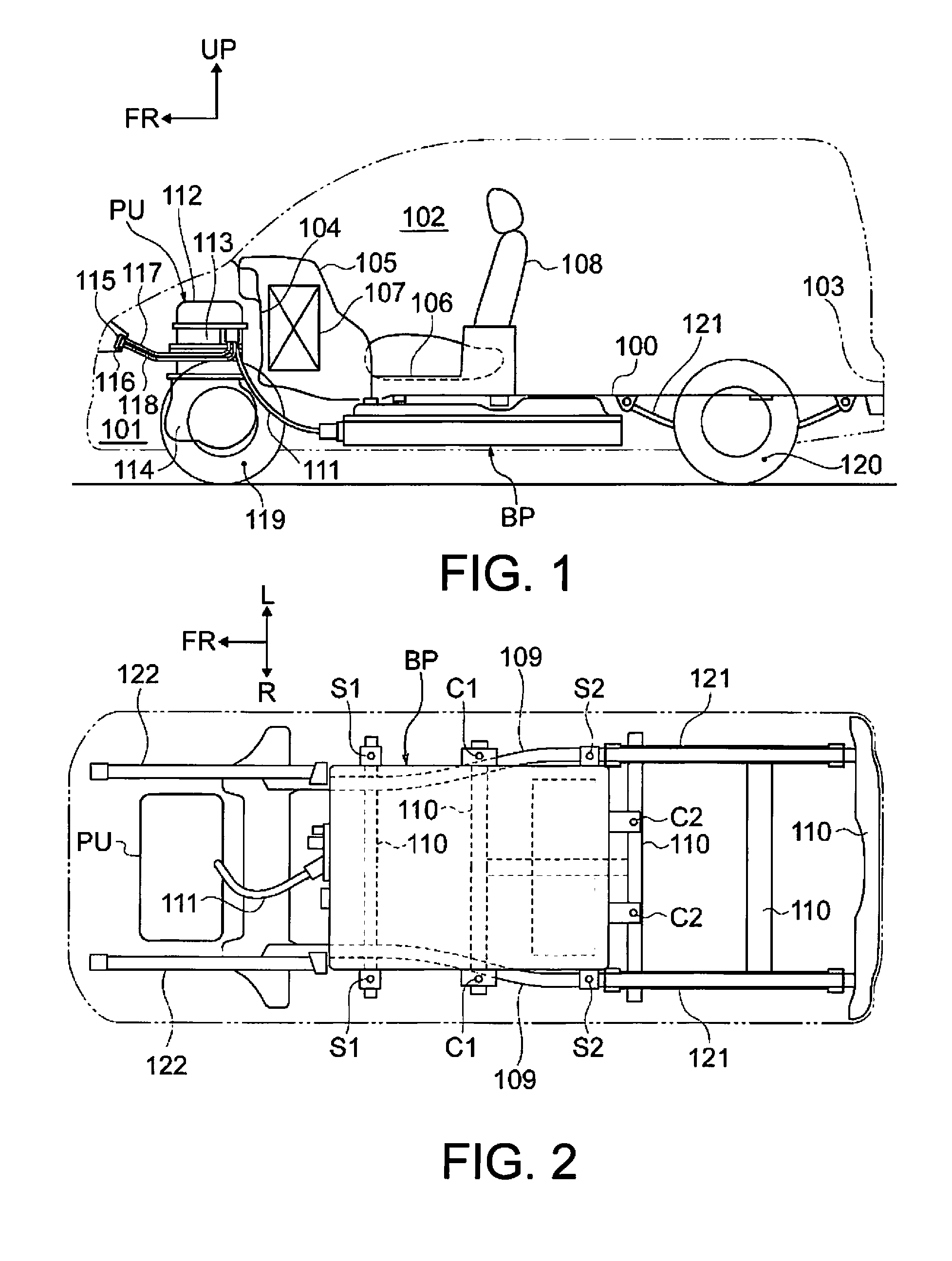
[0029]FIGS. 1 and 2 are a schematic side view and a schematic bottom view, showing an electric car of minivan type with the vehicle installed battery pack of the first embodiment installed. The schematic configuration of an electric car with a battery pack installed will be described below on the basis of FIGS. 1 and 2.

[0030]As shown in FIGS. 1 and 2, the electric car is defined by a floor panel 100 and a dashboard panel 104 into a motor compartment 101 and a passenger compartment 102. A battery pack BP is arranged below the floor...


PUM

PropertyMeasurementUnit
internal stress concentrationaaaaaaaaaa
pressureaaaaaaaaaa
perimeteraaaaaaaaaa

Abstract

A vehicle installed battery pack is provided with a pressure release structure. The vehicle installed battery pack includes a battery pack case, a battery pack module. The battery pack case includes a battery pack lower frame and a battery pack upper cover. The battery pack module is disposed in the battery pack lower frame. The battery pack upper cover is securely joined to the battery pack lower frame via a seal member that extends continuously about an entire perimeter of respective outside peripheral edge portion of the battery pack upper cover. The battery pack upper cover includes a deforming stepped portion having a height difference at least in a heightwise direction; and a weakly joined portion having a lower joint strength than other joined portions being set in an area of the seal member extending continuously about the entire perimeter. The area corresponds to the deforming stepped portion.

Description

CROSS-REFERENCE TO RELATED APPLICATIONS[0001]This application is a U.S. National stage application of International Application No. PCT / JP2013 / 072216, filed Aug. 20, 2013, which claims priority to Japanese Patent Application No. 2012-202472 filed in Japan on Sep. 14, 2012. The entire disclosure of Japanese Patent Application No. 2012-202472 is hereby incorporated herein by reference.BACKGROUND[0002]1. Field of the Invention[0003]The present invention relates to a pressure release structure for a vehicle installed battery pack which is installed in an electric vehicle as a source of propulsive power for the vehicle.[0004]2. Background Information[0005]Vehicle installed battery packs in which the opening of a case member is covered with a cover member, a sealing member is interposed between the case member and the cover member, and a case chamber is hermetically sealed are known in the prior art (e.g., refer to Japanese Laid-Open Patent Application No. 2010-232330).SUMMARY[0006]Howeve...

Claims


Application Information

Patent Timeline
Patent Type & Authority Applications(United States)
IPC IPC(8): H01M2/12H01M2/10H01M50/271
CPCH01M2/1241H01M2220/20H01M2/1083H01M2/1077H01M50/3425H01M50/271Y02E60/10
Inventor ONODERA, TAKESHISUZUKI, NOBUYOSHI
Owner NISSAN MOTOR CO LTD
Why Eureka
Try Eureka