Joining method for metal members

a jointing method and metal member technology, applied in the direction of manufacturing tools, welding/cutting media/materials, welding apparatus, etc., can solve the problems of fracture and insufficient strength of the joint structure of metal members, and achieve the effect of deteriorating strength of the joint structur

Inactive Publication Date: 2010-10-21
HONDA MOTOR CO LTD
View PDF2 Cites 5 Cited by
  • Summary
  • Abstract
  • Description
  • Claims
  • Application Information

AI Technical Summary

Benefits of technology

[0011]Therefore, reaction of the Al primary crystal and the Fe-based metal member due to direct contact thereof does not occur, so that in the joint structure obtained by the joining method, intermetallic compound layer of FeAl-based compound cannot be formed at the boundary portion between the Fe-based metal member and the joint layer. In the conventional technique, intermetallic compound layer at the boundary portion between the Fe-based metal member and the joint layer may be brittle, so that strength of the joint structure may be deteriorated. In contrast, in the embodiment of the present invention, formation of intermetallic compound layer can be prevented, so that the strength at the boundary portion between the Fe-based metal member and the joint layer can be improved.
[0012]According to the joining method of the present invention, since intermetallic compound layer cannot be formed at the boundary portion between the Fe-based metal member and the joint layer, the strength at the boundary portion between the Fe-based metal member and the joint layer can be improved and another effect can be obtained.

Problems solved by technology

However, an intermetallic compound layer, which is formed at a boundary portion between the Fe-based metal member and the joint layer, is brittle, so that fracture may occur thereat.
As a result, strength of the joint structure of metal members may be insufficient.

Method used


Image

  • Joining method for metal members
  • Joining method for metal members
  • Joining method for metal members

Examples


examples

[0037]The present invention will be explained in detail with reference to specific examples.

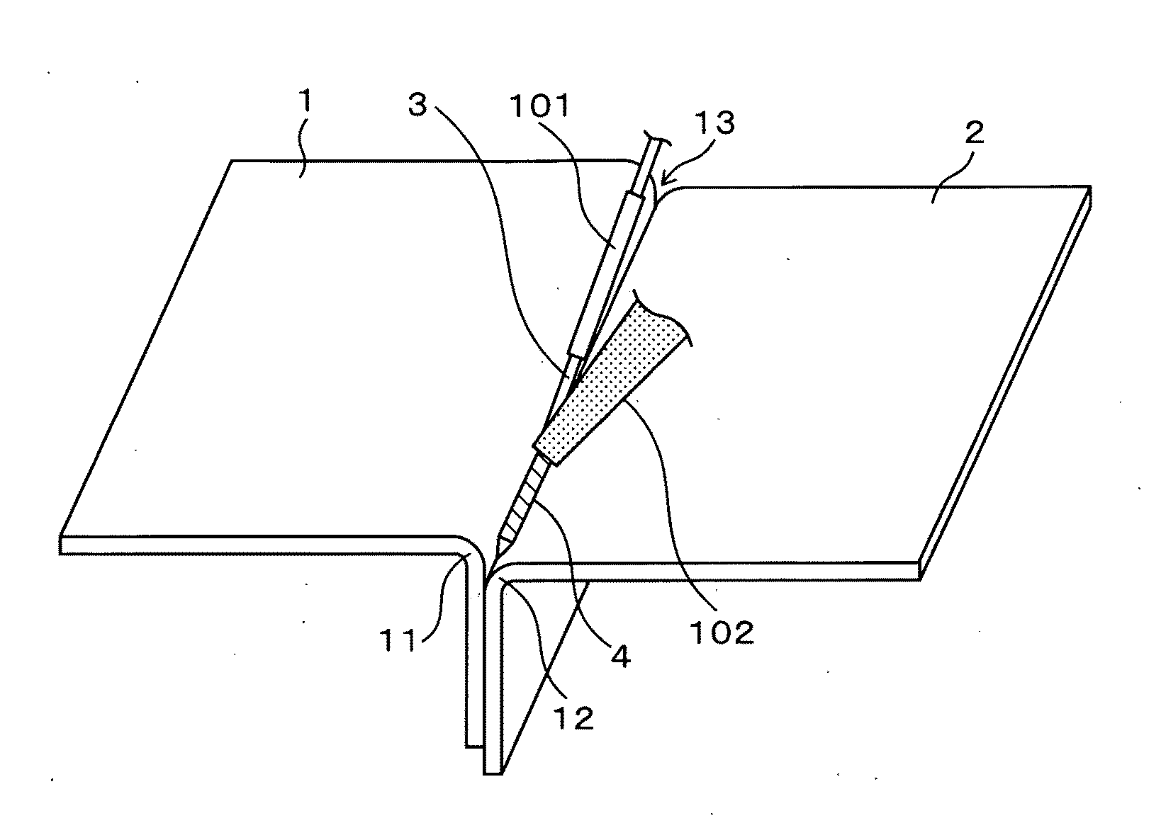
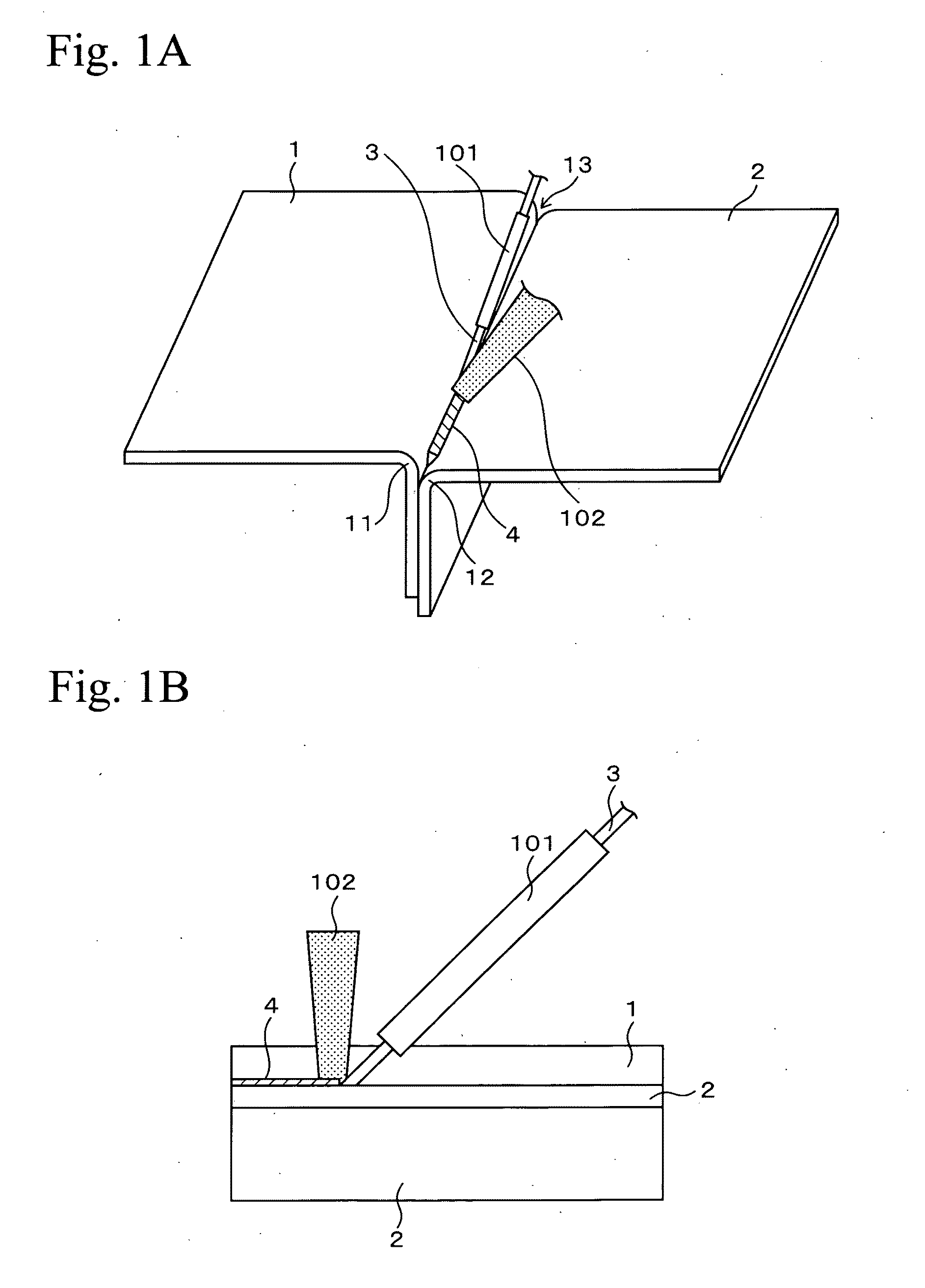
[0038]In samples 11 and 21 and comparative samples 12, 31 and 32, an Fe-based metal member and an Al-based metal member were disposed in the same manner as the layout in FIGS. 1A and 1B, and a groove shape was formed by curved portions thereof. While a Zn-based brazing filler metal, which had a wire shape, was supplied to a center portion of the groove shape through a wire guide, laser beam was irradiated onto a leading end portion of the Zn-based brazing filler metal. Thus, joint structures of the metal members were produced. Table 1 shows conditions of the joining.

[0039]In the samples 11 and 21 and the comparative samples 12, 31 and 32, as shown in Table 1, the content of Al included in the Zn-based brazing filler metal and the heat input condition were mainly varied. In Table 1, regarding the material of the Zn-based brazing filler metal, the included content (added content, wt %) of Al in...


PUM

PropertyMeasurementUnit
mass %aaaaaaaaaa
thicknessaaaaaaaaaa
thicknessaaaaaaaaaa

Abstract

The present invention provides a joining method for metal members, including: preparing an Fe-based metal member of Fe-based material, and an Al-based metal member of Al-based material; providing a Zn-based brazing filler metal between the Fe-based metal member and the Al-based metal member; and joining the Fe-based metal member and the Al-based metal member, wherein the Zn-based brazing filler metal includes: 2.0 mass % or less of Al; and the balance of Zn and inevitable impurities, and in the joining, the Zn-based brazing filler metal is heated such that a liquid phase of the Zn-based brazing filler metal is generated, and in solidification of the Zn-based brazing filler metal in a condition of the liquid phase, Zn primary crystal or eutectic of Zn and Al is crystallized.

Description

BACKGROUND OF THE INVENTION[0001]1. Field of the Invention[0002]The present invention relates to a joining method for metal members in which a Fe-based metal member and an Al-based metal member are joined via a Zn-based brazing filler metal. In particular, it relates to an improvement in a heating technique during joining of them.[0003]2. Description of Related Art[0004]Joint structures (for example, various joints) of metal members are produced by joining of dissimilar metal members. In joining of dissimilar metal members, brazing is performed such that laser beam is irradiated on a brazing filler metal provided between the dissimilar metal members and the brazing filler metal is heated. Thus, a joint layer is formed between the dissimilar metal members, so that a joint structure of metal members is formed.[0005]For example, when a Fe-based metal member of Fe-based material and an Al-based metal member of Al-based material are used, Al and Zn do not form a compound layer, and they ...

Claims


Application Information

Patent Timeline
Patent Type & Authority Applications(United States)
IPC IPC(8): B23K1/20
CPCB23K1/19B23K2203/20B23K35/282B23K2103/20
Inventor WAKISAKA, TAISEISUZUKI, TAKANORIOKUMURA, TOKUJI
Owner HONDA MOTOR CO LTD
Why Eureka
Try Eureka