Amplifier arrangement with limiting module

a technology of limiting module and amplifier, which is applied in the direction of transducer details, volume compression/expansion in digital/coded amplifiers, amplifiers, etc., can solve the problems of audio amplifiers that have limitations in respect of the maximum possible output voltage or the maximum possible output current for the output signal, and achieves the reduction of hardware complexity, simple and robust estimation of operating voltage, and increased loudness

Active Publication Date: 2015-07-23
ROBERT BOSCH GMBH
View PDF4 Cites 0 Cited by
  • Summary
  • Abstract
  • Description
  • Claims
  • Application Information

AI Technical Summary

Benefits of technology

[0013]In this case, it is of particular advantage that the response of the limiting module is stipulated in the digital data processing device in programmable fashion, particularly user-programmable fashion, and not by means of circuitry. It is thus possible for linear and nonlinear characteristics, look-up tables, functions, predictors, observers, etc. to be able to be used in the limiting module for determining the gain parameter.
[0014]The hardware complexity is also reduced by virtue of not measuring the actual audio output signal downstream of the amplifier apparatus but rather using the operating voltage parameter to estimate only the at least one operating voltage and taking the estimated operating voltage and the estimated audio output signal as a basis for adjusting the gain parameter. The at least one operating voltage usually changes only very slowly in comparison with changes in the audio input signal or in the audio output signal, which means that the estimation of the operating voltage is very simple and robust.
[0015]The effect achieved by supplying an operating voltage parameter from the instantaneous value of the operating voltage to the conditioning apparatus, particularly the limiting module, is that the amplifier apparatus can also be operated using power supply units that have no voltage stabilization or operating voltages that change or fluctuate on the basis of a mode. The effect achieved by this is that the amplifier arrangement, particularly the audio output signal, is not driven uncontrolledly or unintentionally into a clipping range even if the operating voltage fluctuates.
[0016]In a preferred embodiment of the invention, the gain parameter is adjusted such that the peak-to-peak value (peak-to-peak amplitude) of the estimated audio output signal is less than or equal to the amplitude of the estimated operating voltage or the total amplitude of the estimated operating voltages as an operating voltage limit or limits. The effect achieved by this is that the audio output signal cannot or cannot continuously exceed the operating voltage limits conditional upon the operating voltage or operating voltages, which means that the clipping described previously is avoided.
[0017]In a preferred development of the invention, the gain parameter is adjusted in the event of a transgression above an operating voltage limit, which is provided by the estimated operating voltage(s), by the estimated audio output signal using tracking of the gain parameter with a delay time. This delay time corresponds particularly to an attack time that describes the interval of time after which the audio output signal is controlled down to the operating voltage limits following a transgression above the operating voltage limit. The delay time is preferably chosen to be greater than 1 millisecond and less than 10 milliseconds, as a result of which the actual audio output signal is driven in the clipping range, particularly cut off, for the delay time. This refinement has the advantage that the perceived overdriving of the amplifier apparatus is usually not found to be disturbing from a psychoacoustic point of view, but there is a desirable sensation of increased loudness.
[0018]In a preferred refinement of the invention, the limiting module has an amplifier model for estimating the audio output signal. In the simplest case, the amplifier model may be in the form of a linear gain factor, with the input audio signal and / or intermediate signal multiplied by the gain factor forming the audio output signal. However, it is also possible for the amplifier model to be in more complex, in particular nonlinear, form in order to be able to map the precise gain characteristics of the amplification apparatus and thereby to be able to improve the prediction quality of the estimated audio signal.

Problems solved by technology

Any audio amplifier has limitations in respect of the maximum possible output voltage or the maximum possible output current for the output signal.

Method used


Image

  • Amplifier arrangement with limiting module
  • Amplifier arrangement with limiting module
  • Amplifier arrangement with limiting module

Examples


Embodiment Construction

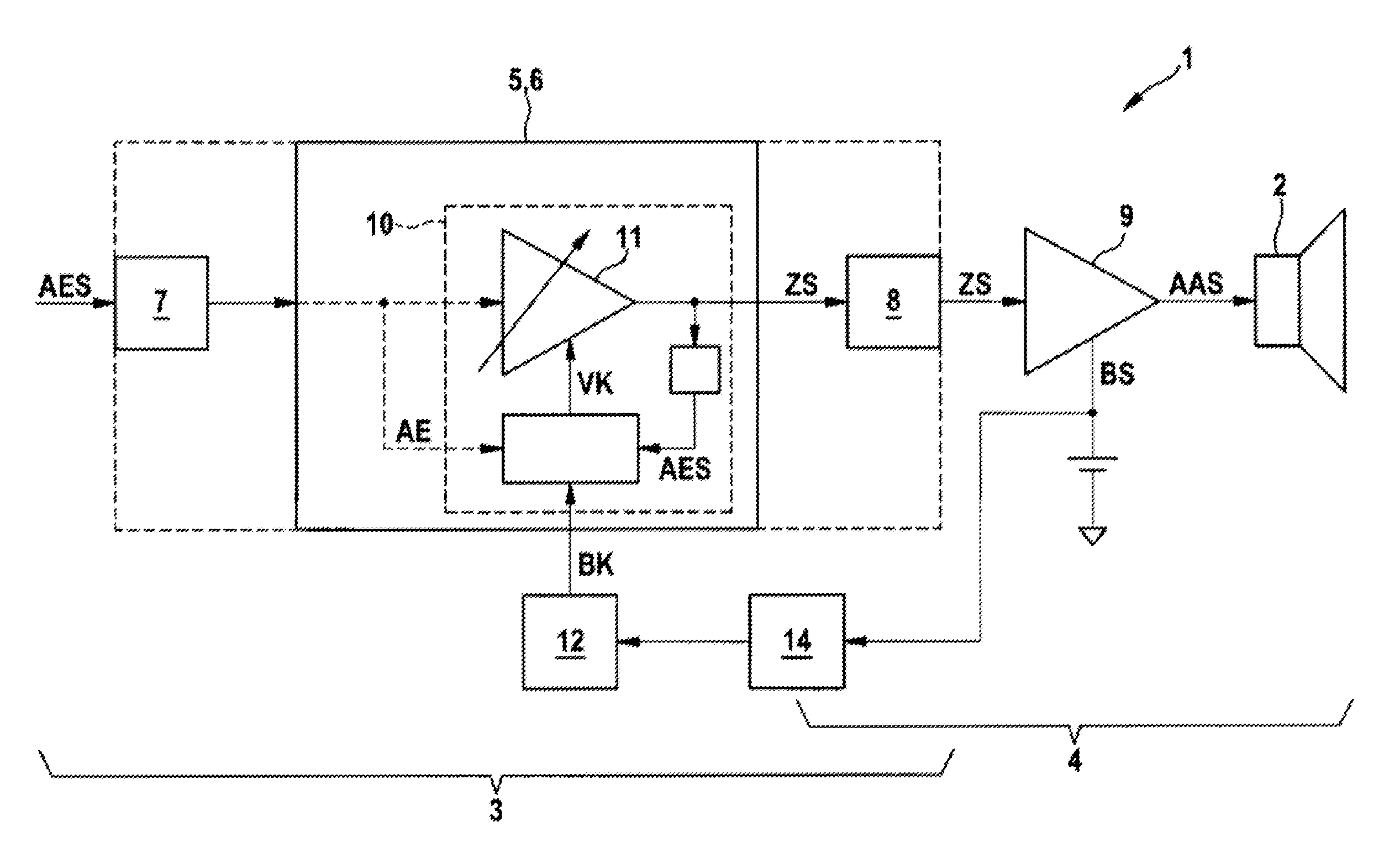
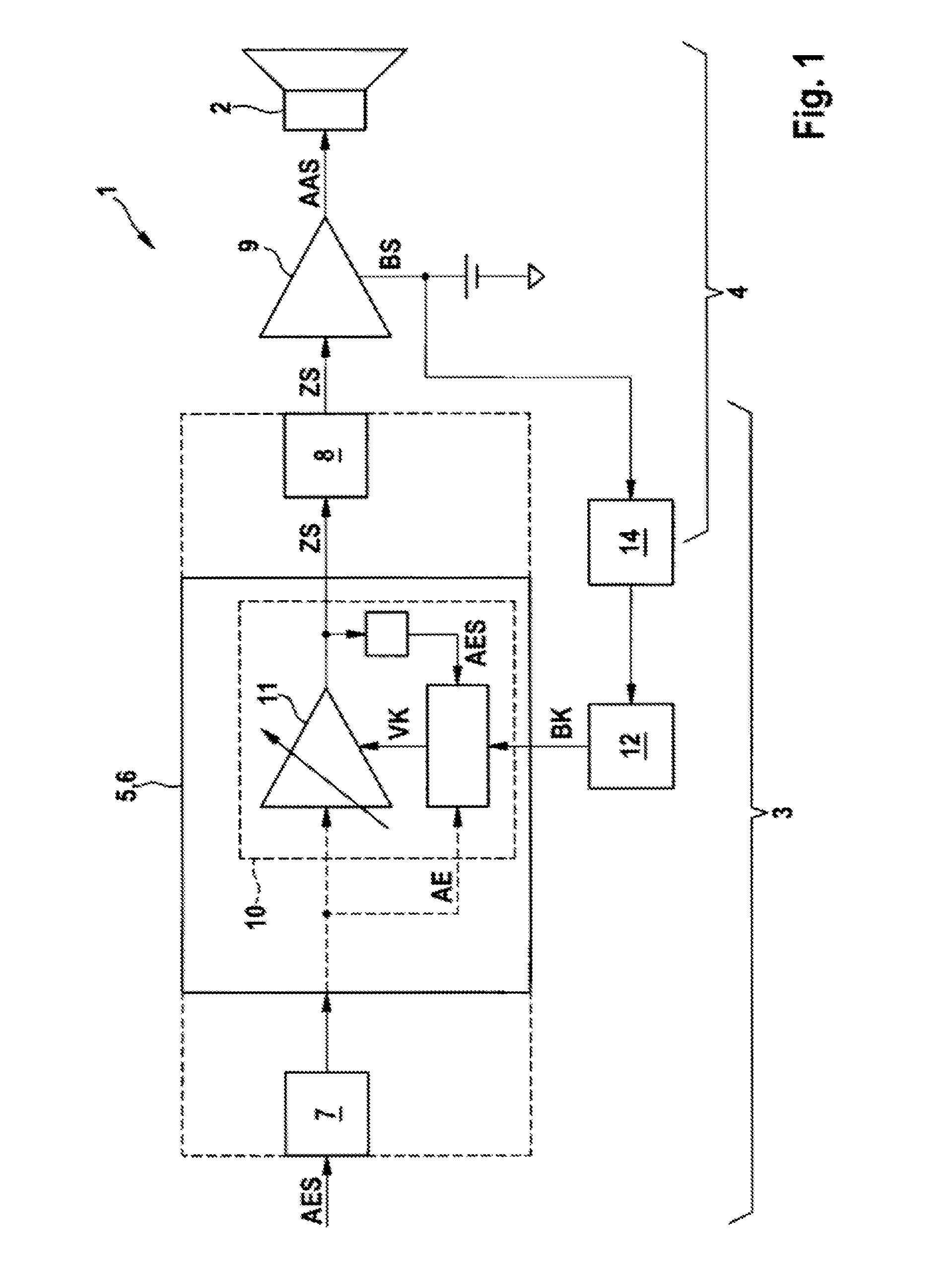
[0028]FIG. 1 shows a schematic block diagram of an amplifier arrangement 1 as an exemplary embodiment of the invention. The amplifier arrangement 1 is used to amplify an audio input signal AES and to supply it as an audio output signal AAS to an electromechanical sound transducer, such as a loudspeaker 2. Optionally, the loudspeaker 2 forms a portion of the amplifier arrangement 1. By way of example, the amplifier arrangement 1 is used to amplify music or speech. By way of example, an amplifier arrangement 1 is used to provide sound for a restaurant, a discotheque or else a conference hall. The output power of the audio output signal AAS that is applied to the loudspeaker 2 is greater than 10 watts or greater than 50 watts, the output power being the maximum continuous power that can be delivered with the rated impedance connected when supplied with pink noise, according to DIN 45324.

[0029]By way of example, the audio input signal AES comes from a microphone or another audio source,...


PUM


Abstract

An amplifier arrangement for amplifying an audio input signal AES into an audio output signal AAS, having a conditioning apparatus for converting the audio input signal AES into a conditioned intermediate signal ZS. The conditioning apparatus includes an audio input interface for accepting the audio input signal and a digital data processing device. The amplifier arrangement also includes an amplifier apparatus for amplifying the intermediate signal ZS into the audio output signal AAS and the amplifier apparatus has at least one operating voltage BS. The amplifier arrangement also includes a limiting module for limiting the audio output signal AAS by changing a gain parameter VK.

Description

BACKGROUND OF THE INVENTION[0001]The invention relates to an amplifier arrangement for amplifying an audio input signal into an audio output signal.[0002]Audio amplifiers are generally used to amplify an input signal in linear fashion and to output it as an output signal, for example for a loudspeaker, with a higher amplitude than the input signal. Any audio amplifier has limitations in respect of the maximum possible output voltage or the maximum possible output current for the output signal. If the audio amplifier is taken to these limits by means of overdriving, limiters are usually used in order to reduce distortions in the output signal to a tolerable degree. In the event of overdriving of an audio amplifier that results in the maximum possible output voltage being exceeded, voltage limiters are used in order to avoid what is known as clipping in the output signal.[0003]The document EP 230 1148 B1, which probably forms the closest prior art, discloses an audio amplifier for amp...

Claims


Application Information

Patent Timeline
Patent Type & Authority Applications(United States)
IPC IPC(8): H03F3/181
CPCH03F3/181H03F2200/321H03G7/007H03G11/008
Inventor PLAGER, JOSEFENGL, PATRICKSTEIN, THOMAS
Owner ROBERT BOSCH GMBH
Why Eureka
Try Eureka