Camera module for a vehicle and method for its production

a technology for camera modules and vehicles, applied in the field of camera modules for vehicles, can solve the problems of determining the axis of view relative to the camera housing, affecting the production efficiency of the camera housing, and requiring a large number of components to meet the tolerances, etc., and achieves the effects of low production cost, high degree of precision, and low number of components

Inactive Publication Date: 2015-07-23
ROBERT BOSCH GMBH
View PDF9 Cites 16 Cited by
  • Summary
  • Abstract
  • Description
  • Claims
  • Application Information

AI Technical Summary

Benefits of technology

[0018]According to the present invention, in this way a rapid, secure, precise, and low-cost production is enabled. This enables a compact form with a low number of components that can be produced with a high degree of precision.

Problems solved by technology

In general, the expensive production from a large number of components having corresponding tolerances, and the problem of determining the axis of view relative to the camera housing, are disadvantageous.

Method used


Image

  • Camera module for a vehicle and method for its production
  • Camera module for a vehicle and method for its production
  • Camera module for a vehicle and method for its production

Examples


Embodiment Construction

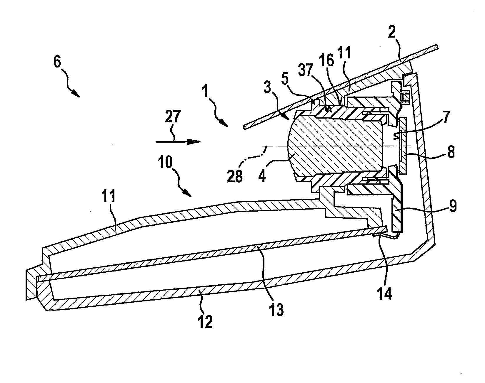
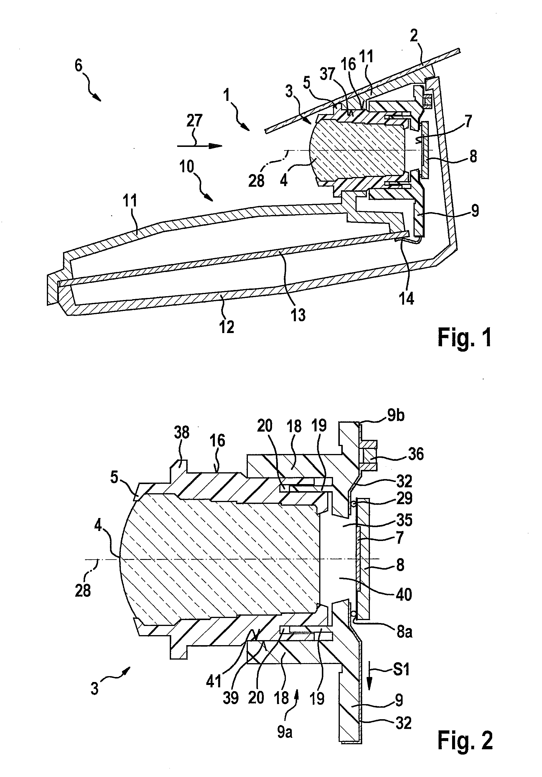
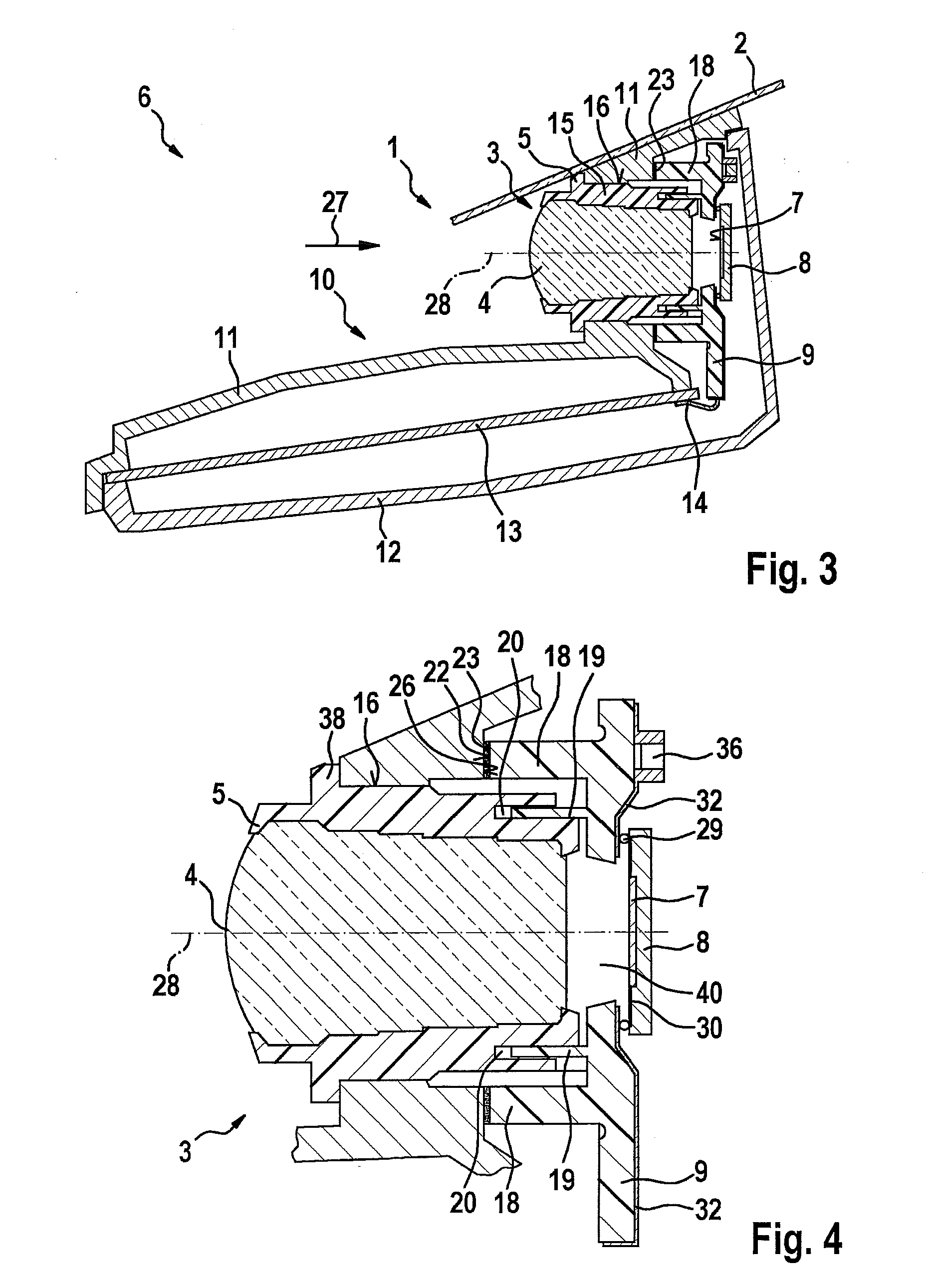
[0027]Camera module 1 of FIGS. 1, 2, and 3 is in each case attached behind a vehicle windshield 2, in particular a front windshield or rear windshield of a vehicle 6 (not shown in more detail). Radiation 27, in particular light in the visible range or also in the IR range, is received by camera module 1. Radiation 27 can in particular enter through vehicle windshield 2, i.e. can come from outside the vehicle, and / or can come from the interior of the vehicle for interior monitoring; in addition, if a sensor system of the windshield outer surface is present it is also for example possible to couple light into vehicle windshield 2 and for this light to subsequently be sensed by camera module 1.

[0028]Camera module 1 has:

[0029]an objective 3 having a lens mount 5 and having at least one lens 4 accommodated in lens mount 5, an image sensor 8, a bearer device 9, and a camera housing 10. In addition, for example a camera mount can be provided for fastening camera housing 10 on vehicle winds...


PUM

PropertyMeasurementUnit
flexibleaaaaaaaaaa
longitudinal displacementaaaaaaaaaa
widthaaaaaaaaaa

Abstract

A camera module, in particular for a vehicle, the camera module having at least: an objective having a lens mount and at least one lens, an image sensor for acquiring and converting optical signals into electrical signals, a bearer device on which the image sensor is mounted and contacted, and a camera housing for accommodating the objective and the bearer device. The objective is connected to the camera housing, in particular to a first housing part, and is borne by the camera housing. The bearer device can in particular be fixed on the objective or on the first housing part.

Description

FIELD OF THE INVENTION[0001]The present invention relates to a camera module for a vehicle and a method for its production.BACKGROUND INFORMATION[0002]Camera modules for vehicles have in general an objective having a lens mount and at least one lens, an image sensor, and a bearer device on which the image sensor is mounted and contacted. For this purpose, the bearer device is fashioned for example as a circuit board. The objective is accommodated in an objective receptacle (lens holder) so as to be capable of longitudinal displacement in order to enable adjustment. The objective receptacle is generally fastened on the bearer device.[0003]The adjustment takes place by acquiring for example a test pattern in a relevant object width, and evaluating the image signals of the image sensor in order to determine a longitudinal position of the objective with the best possible contrast and to adjust it so that the image sensor is in the image plane. Subsequently, the objective is fixed on the...

Claims


Application Information

Patent Timeline
Patent Type & Authority Applications(United States)
IPC IPC(8): H04N5/225B60R11/04
CPCH04N5/2254B60R2011/0026B60R11/04H04N5/2252Y10T29/49826H04N23/51H04N23/54H04N23/57
Inventor FRITZ, STEFFENAPEL, UWESEGER, ULRICH
Owner ROBERT BOSCH GMBH
Why Eureka
Try Eureka