Cosmetic Dispenser with Frictional Resistance

a dispenser and friction technology, applied in the field of cosmetic dispensers, can solve the problems of perceived lack of quality of devices, lipstick products can also be perceived as inferior, and retained products, so as to avoid the potentially deleterious effects of them

Active Publication Date: 2015-07-30
HCP PACKAGING USA
View PDF1 Cites 13 Cited by
  • Summary
  • Abstract
  • Description
  • Claims
  • Application Information

AI Technical Summary

Benefits of technology

[0012]A further object of the invention is to provide a cosmetic dispenser that is operative without a need for the introduction of lubricant into the system thereby avoiding the potentially deleterious effects thereof.
[0013]Another object of embodiments of the invention is to provide a cosmetic dispenser that demonstrates a frictional drag during operation of the dispenser to impart a firm feel to the user and provides an impression of quality and luxury during operation.
[0014]Still another object of embodiments of the invention is to provide such a cosmetic dispenser that is relatively efficient in construction, assembly, and operation.
[0015]An additional object of embodiments of the invention is to provide a cosmetic dispenser that does not exhibit significant static friction when relative movement of the components of the dispenser is initiated and that emits minimized noise during operation to give a sound and feel of quality.
[0020]As disclosed herein, a cap could be fixed to the base portion of the inner body, and the second annular bearing surface could be formed by a portion of the cap. The cap could, for example, be retained by an annular ridge and facets on the base portion of the inner body to prevent inadvertent longitudinal and rotational displacement of the cap. In other embodiments, the second annular bearing surface could be formed by an annular ridge retained by the inner body, such as by being formed integrally therewith.

Problems solved by technology

While effective for its essential purpose, this basic lipstick dispensing design has demonstrated plural disadvantages that have been well recognized in the cosmetic industry.
For example, there can be axial and radial looseness between the various components of the lipstick dispenser that can lead to a perceived lack of quality of the device and, by inference, the retained product.
The lipstick product can also be perceived as being inferior when the swivel torque required to operate the dispenser is excessively light or inconsistent.
Still further, a loosely retained elevator cup can wobble thereby resulting in damage to the product and again reducing the perceived quality thereof.
It has been found, however, that the tabs and ribs can plastically deform over time thereby losing effectiveness.
Additionally, certain of these arrangements can yield an inconsistent swivel torque during travel of the elevator cup since the effective diameter of the relatively moveable components can vary along their length thereby changing the frictional drag in an undesirable manner.
For example, under many prior art mechanisms, the existence of multiple points or locations for generating frictional torque renders it more difficult to control the torque within desired swivel torque ranges.
If the swivel torque is too high, then the machine may turn the elevator cup out of the track on the spiral cam.
If the torque is too low, the cosmetic dispenser will feel cheap, and the elevator cup will have a tendency to move when the dispenser is not in use.
Even if those benefits are achieved, however, the introduction of lubrication creates other issues.
For instance, swivel torque can be rendered undesirably low, and lubricant can sometimes get on to the pomade or on the outside of the case.

Method used


Image

  • Cosmetic Dispenser with Frictional Resistance
  • Cosmetic Dispenser with Frictional Resistance
  • Cosmetic Dispenser with Frictional Resistance

Examples


Embodiment Construction

[0047]The cosmetic dispenser disclosed herein is subject to a wide variety of embodiments. However, to ensure that one skilled in the art will be able to understand and, in appropriate cases, practice the present invention, certain preferred embodiments of the broader invention revealed herein are described below and shown in the accompanying drawing figures. Therefore, before any particular embodiment of the invention is explained in detail, it must be made clear that the following details of construction and illustrations of inventive concepts are mere examples of the many possible manifestations of the invention.

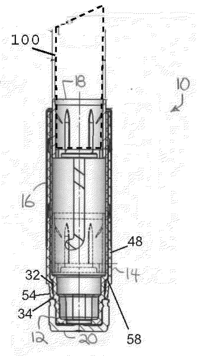
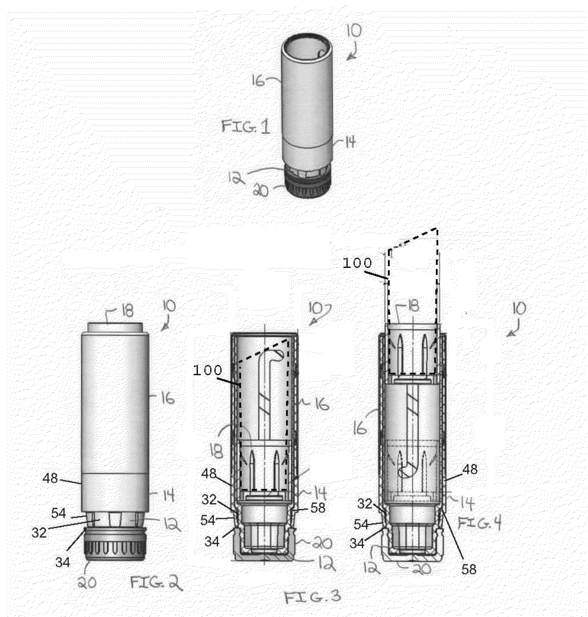
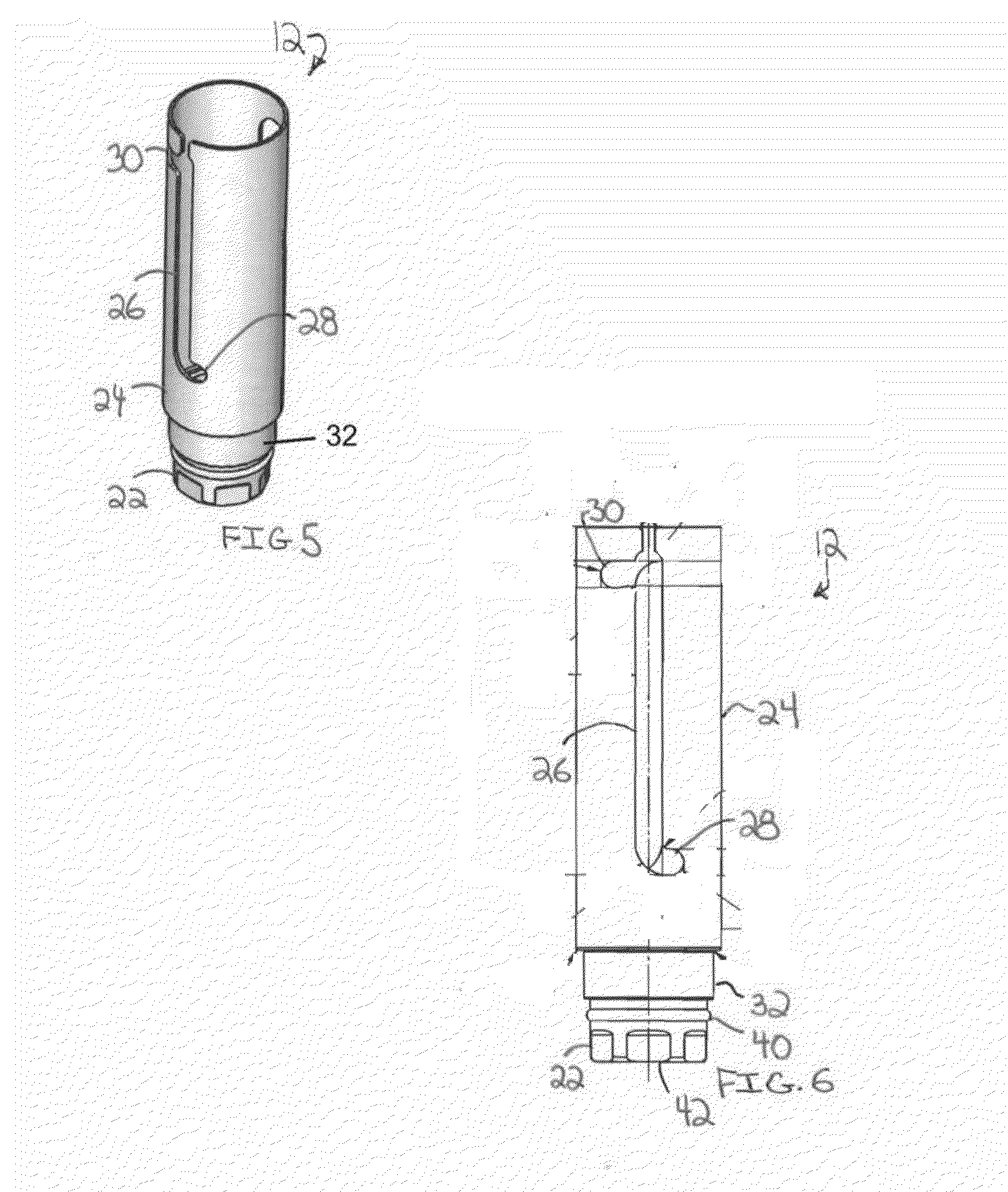
[0048]With this in mind and looking more particularly to the accompanying figures, a first exemplary embodiment of a cosmetic dispenser pursuant to the present invention is indicated generally at 10 in FIGS. 1 through 4. The cosmetic dispenser 10 is founded on a tubular inner body 12 that is rotatably engaged with a spiral member 14. As will be described more fully herein...


PUM


Abstract

A cosmetic dispenser with an inner body rotatably engaged with a spiral member. An elevator cup retains a cosmetic pomade, and the spiral member has spiral formations along an inner surface thereof for engaging lugs of the elevator cup that pass through longitudinal tracks in the inner body. The inner body can have lateral and longitudinal bearing surfaces with the lateral bearing surface aligned longitudinally with a longitudinal axis of relative rotation of the spiral member and the inner body and the longitudinal bearing surface orthogonal thereto. Fingers can project inwardly from the inner body to be in slidable, frictional contact with both the longitudinal and lateral bearing surfaces so that the fingers are restrained laterally and longitudinally. The fingers can be inwardly angled establish an effective circumference with the fingers tangent thereto smaller than the circumference of the lateral bearing surface.

Description

FIELD OF THE INVENTION[0001]The present invention relates generally to cosmetic containers and dispensers. Stated more particularly, disclosed herein is a device for containing and dispensing cosmetics with a frictional resistance exhibited between relatively rotatable inner body and spiral member components.BACKGROUND OF THE INVENTION[0002]In a typical prior art lipstick dispenser, an elevator cup retains a body of lipstick for axial extension and retraction by a swiveling of a base portion in relation to a body portion of the dispenser. Dispensers have commonly employed a cam member with helical threads formed therealong that is rotatably associated with a tubular inner body. The inner body is normally formed with opposed longitudinal tracks. The elevator cup typically has opposed lugs that are received through the longitudinal track and associated with the helical threads of the cam member. Under this arrangement, a rotation of the cam member in relation to the tubular innerbody ...

Claims


Application Information

Patent Timeline
Patent Type & Authority Applications(United States)
IPC IPC(8): A45D40/04
CPCA45D40/04A45D40/06
Inventor HOLLOWAY, THOMAS F.
Owner HCP PACKAGING USA
Why Eureka
Try Eureka