Anchoring device for a spinal implant, spinal implant and implantation instrumentation

a technology for anchoring devices and spinal implants, applied in the field of orthopaedic implants, can solve the problems of the inability to adjust the anchoring device, so as to reduce the risk of weakening the implant, improve the reliability, and improve the stability

Active Publication Date: 2015-07-30
LDR MEDICAL
View PDF42 Cites 75 Cited by
  • Summary
  • Abstract
  • Description
  • Claims
  • Application Information

AI Technical Summary

Benefits of technology

[0029]Another purpose of some embodiments incorporating various technical features disclosed in the present application is to mitigate at least one of the disadvantages of the prior art by proposing spinal implants adapted to be secured by anchoring devices according to various embodiments of this disclosure, and that are (more) compact (little cumbersome) and/or with the possibility of removal is improved and/or which offers better reliability (increased stability and anchor the implant and/or reduced risk of weakening the implant). Furthermore, some embodiments are also intended to address various problems by providing an implantable spinal implant easily, for example by way of approach along an axis substantially perpendicular to the axis of the spine, and which may be attached reliably with a low risk of damage to the vertebrae, especially the posterior tract implantation and/or transforaminal.
[0030]This purpose may be furthered with a spinal implant embodiment including at least one outer surface and at least one verteb

Problems solved by technology

A problem in this field sometimes relates to the stability of the rachidian implants in the discal space once they have been implanted.
Indeed, for example, there can exist a risk that the implant moves in the intervertebral space under the effect of the forces experienced during movement of the patient, even when the implant is provided with catches or teeth on its vertebral contact surfaces.
Another problem in the field sometimes relates to invasivity and access to the intervertebral spaces (discal spaces) which is often delicate because of congestion, notably because of the presence of blood vessels and nerves in the vicinity of the intervertebral space, as well as the proximity of the spinal cord.
Another problem that may exist for the bone anchoring means relates to ablation.
This type of anchoring devices or anchor, including a plate intended to be planted into the bone may sometimes pose a risk of the vertebra being split by the plate, during its impaction in the vertebra or under the effect of the forces exerted on the implant and/or on the anchor o

Method used


Image

  • Anchoring device for a spinal implant, spinal implant and implantation instrumentation
  • Anchoring device for a spinal implant, spinal implant and implantation instrumentation
  • Anchoring device for a spinal implant, spinal implant and implantation instrumentation

Examples


Embodiment Construction

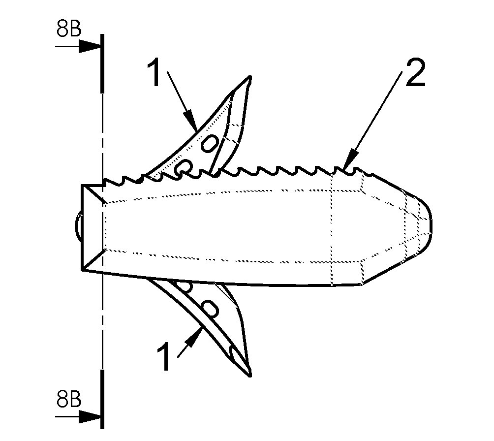
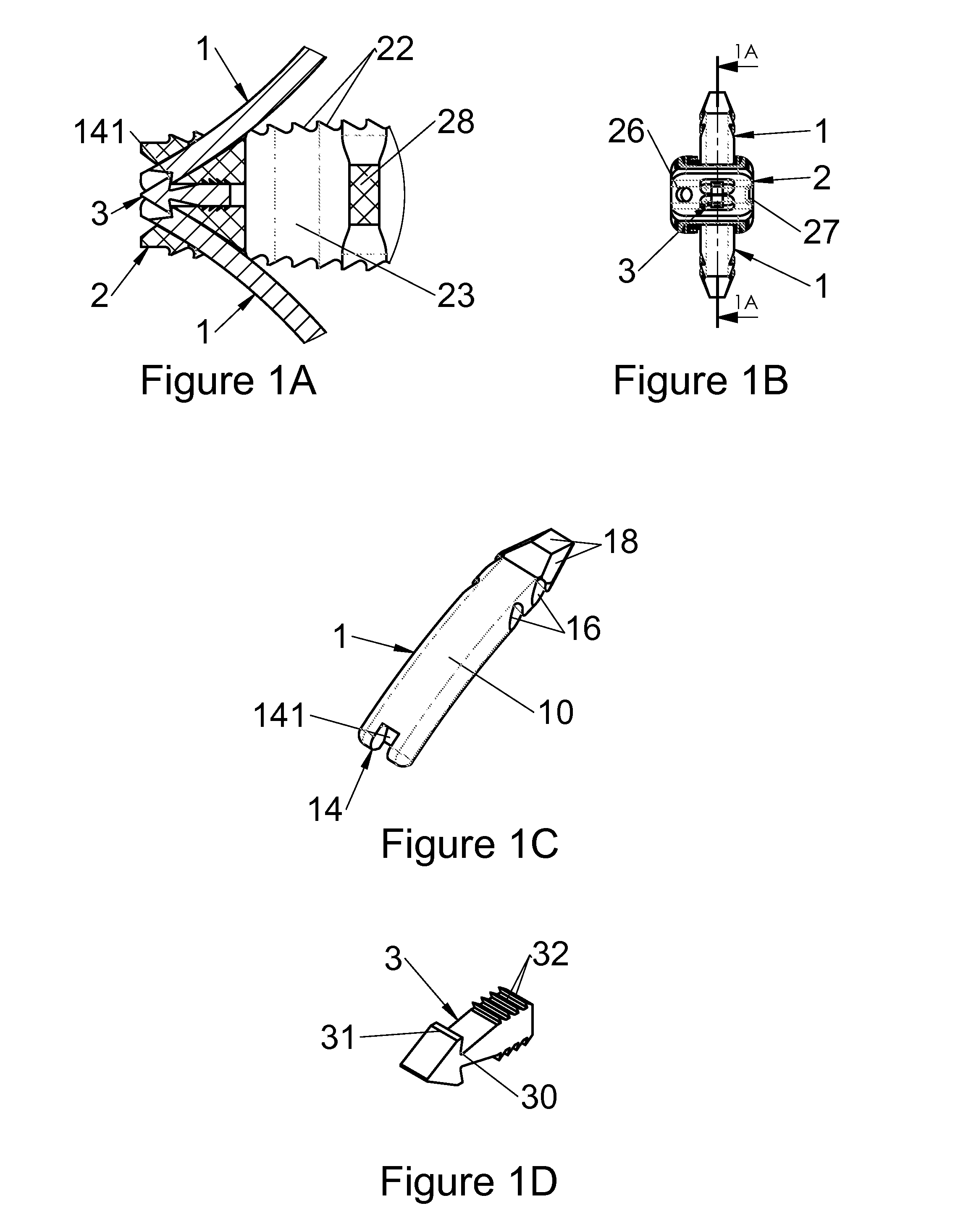
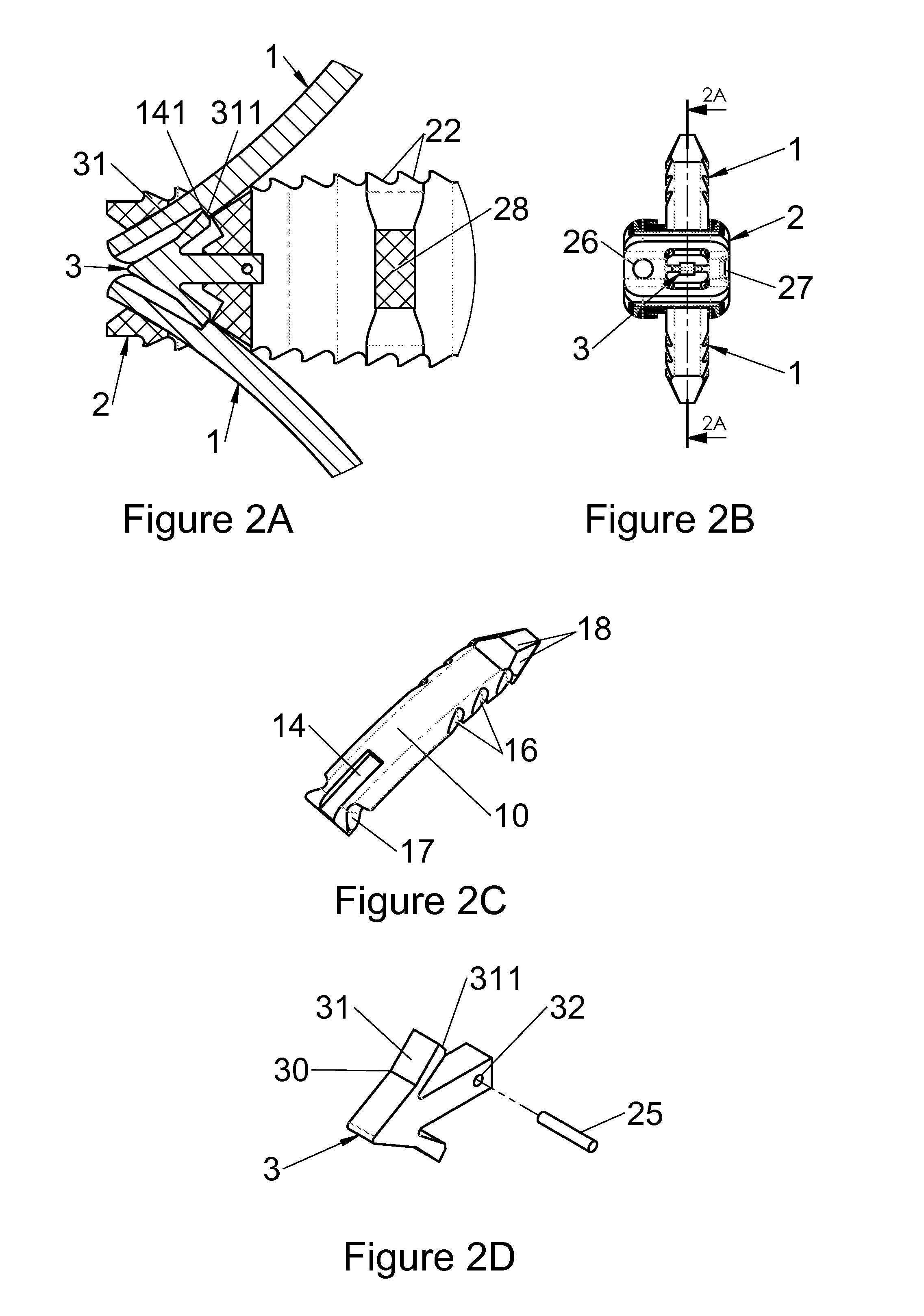
[0100]Various embodiments of this disclosure will now be described with reference to the figures of the present application, which among other subject matter are mostly directed to 3 groups of objects and various combinations thereof:[0101]anchoring devices (1) (or “attachment devices” or further “anchors”), and / or anchoring systems including several anchoring devices (1) which may be identical or different, or even complementary to each other;[0102]intervertebral implants (2) laid out for receiving one or several of such devices (1) or anchoring systems, including but not limited thereto, intersomatic cages configured for an implantation through a posterior or transforaminal route;[0103]instrumentation (3, 4, 5) for implanting these implants (2) between the vertebrae and attaching them with such devices (1) or anchoring systems.

[0104]Each of these groups of objects may include various possible embodiments relating to a given object. Each of the objects include various elements (gen...


PUM


Abstract

Anchoring devices for rachidian implants, implants, surgical instruments, and surgical systems and methods are disclosed. In some embodiments, an anchor comprises a stiff plate with a longitudinal axis, configured for penetration of its anterior end into a vertebral surface while its posterior end remains engaged with the implant. An implant may include a locking mechanism for the anchor. An anchor may include an abutment configured to abut a complementary abutment of an implant. In some configurations, inserting an anchor in a passage of an implant may displace a locking mechanism, which may resile and lock the anchor in the implant with complementary abutments of the anchor and implant abutting.

Description

CROSS-REFERENCE TO RELATED APPLICATIONS[0001]This application claims priority under 35 U.S.C. §119 to French patent application number FR1450749 filed in France on Jan. 30, 2014, which is incorporated herein by reference.BACKGROUND[0002]This disclosure relates to orthopedic implants, in including rachidian (spinal) implants, such as intersomatic cages for example. Intersomatic cages may be implanted between two adjacent vertebrae for placement and growth of bone tissue grafts (or substitute) in the discal space and for obtaining arthrodesis (merging of two vertebrae). For example, after putting the cage into place, the intervertebral space is filled with autologous cancellous bone or suitable bone substitutes which may also (or as an alternative) be placed in a cavity of the cage before its positioning in the space. This disclosure relates to intervertebral implants such as intersomatic cages but also relates to other types of implants such as for example intervertebral disc prosthe...

Claims


Application Information

Patent Timeline
IPC IPC(8): A61B17/70A61F2/44
CPCA61F2/442A61B17/7064A61F2/4425A61F2/447A61F2/4611A61F2/4637A61F2002/30136A61F2002/30161A61F2002/30331A61F2002/30373A61F2002/30401A61F2002/30476A61F2002/30492A61F2002/305A61F2002/30517A61F2002/30579A61F2002/30604A61F2002/30772A61F2002/30782A61F2002/30841A61F2002/30879A61F2002/30889A61F2002/30904A61F2002/4641A61F2/4455
Inventor CHATAIGNER, HERVECHEBUHAR, CRAIGBERNARD, PIERREDINVILLE, HERVEBOUGERE, EMMANUEL
Owner LDR MEDICAL
Why Eureka
Try Eureka