Recording apparatus

Active Publication Date: 2015-07-30
SEIKO EPSON CORP
View PDF2 Cites 4 Cited by
  • Summary
  • Abstract
  • Description
  • Claims
  • Application Information

AI Technical Summary

Benefits of technology

This patent describes a printer that allows for easy feeding of ink to a recording head without increasing the space needed for the overall printer. The printer has a liquid container and a liquid feeding path that connects to the recording head, allowing for easy ink feeding. The liquid container can be easily attached and detached from the printer for replacement without needing to change the installation area. The printer also has a valve mechanism that prevents leakage of ink when the container is detached. The force required to detach the container is minimal, making it easy to manage. The printer also ensures smooth ink feeding even when the container is at a lower position in the machine.

Problems solved by technology

For this reason, there is a problem that the installation area of the entire printer increases by an area equal to the installation area of the liquid container and which must be added to the installation area of the apparatus housing.
When, however, such an arrangement is implemented, since the liquid container requires a replacement task to be performed, there arises a new problem in that, when the replacement task is carried out, connecting the liquid container to the ink feeding tube can become difficult.
In addition, such a problem is relatively common with respect to not only an ink jet printer, but also a recording apparatus configured such that a liquid container, which contains liquid to be fed to a recording head disposed inside the apparatus housing, is also disposed inside the apparatus housing, and a liquid feeding path connecting the liquid container to the recording head is provided.
Further, in such a case, since the liquid container is disposed inside the apparatus housing, the installation area of the entire recording apparatus does not increase.

Method used


Image

  • Recording apparatus
  • Recording apparatus
  • Recording apparatus

Examples


Embodiment Construction

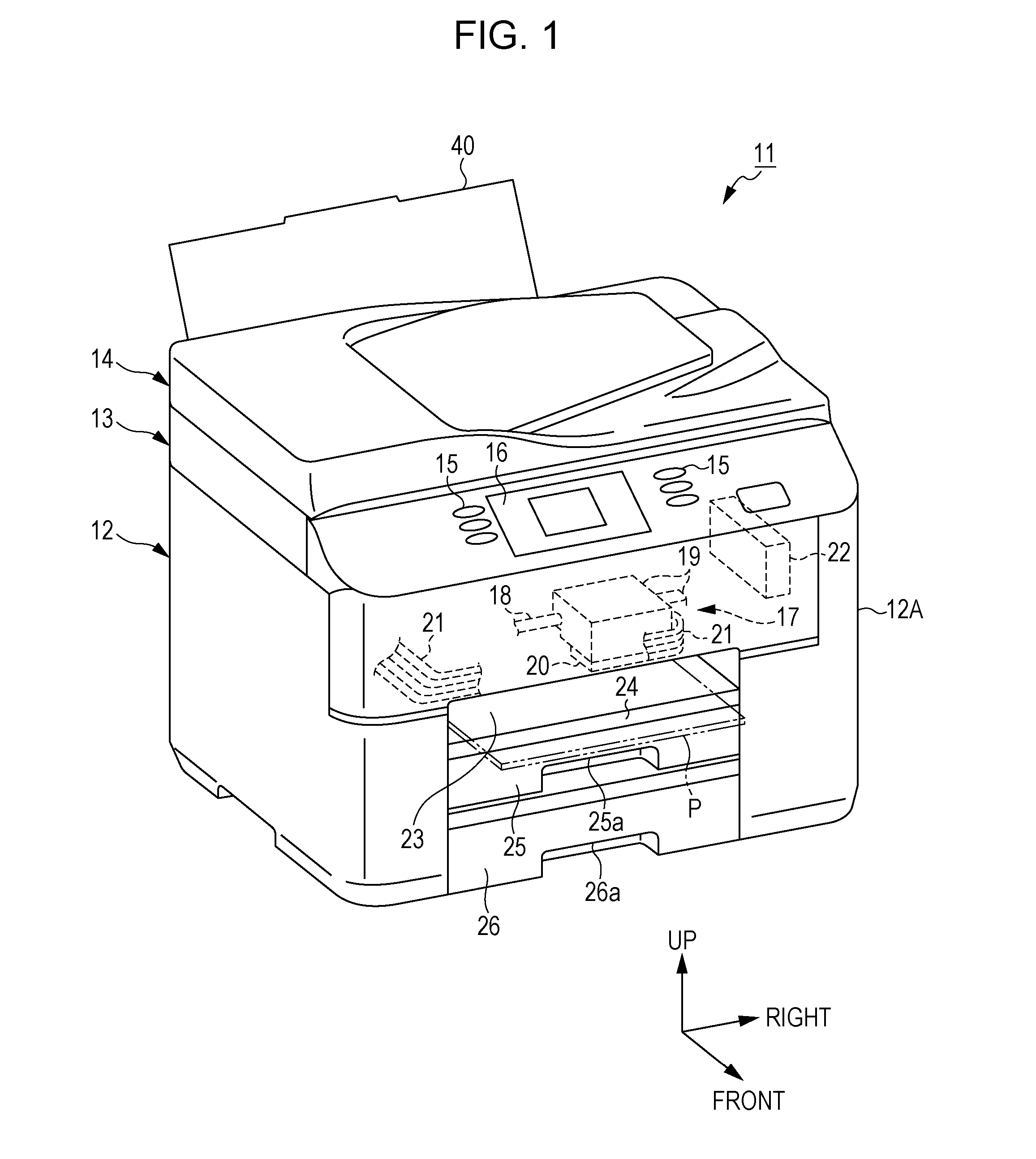
[0031]Hereinafter, a recording apparatus according to an embodiment will be described with reference to the drawings. In addition, the recording apparatus according to this embodiment is, for example, an ink jet printer which performs recording (printing) by ejecting ink, which is an example liquid, onto a medium, such as paper. In addition, hereinafter, when describing a direction, unless otherwise noted, the description will be made on the basis of directions shown in FIG. 1.

[0032]As shown in FIG. 1, a multifunction printer 11 includes a recording apparatus 12 that performs a recording operation by ejecting ink; a reading apparatus 13 that reads information recorded on a printing medium (omitted from illustration); and an automatic printing medium feeding portion 14 capable of feeding a plurality of printing media stacked in layers to the reading apparatus 13 on a sheet-by-sheet basis. The reading apparatus 13 is disposed on a box-shaped apparatus housing 12A of the recording appa...


PUM


Abstract

A recording apparatus includes a recording head that is disposed inside an apparatus housing and that ejects a liquid onto a medium; a liquid container attaching / detaching unit that is configured such that a liquid container which contains the liquid is attached / detached to / from the liquid container attaching / detaching unit itself and that is configured to be inserted / extracted through an inserting / extracting opening provided in the apparatus housing; and a liquid feeding path that feeds the liquid from the liquid container to the recording head. A unit-side path and an apparatus-housing-side path which constitute the liquid feeding path are mutually connected by the insertion of the liquid container attaching / detaching unit through the inserting / extracting opening of the apparatus housing, and the mutual connection is disconnected by the extraction of the liquid container attaching / detaching unit through the inserting / extracting opening of the apparatus housing.

Description

BACKGROUND[0001]1. Technical Field[0002]The present invention relates to a recording apparatus, such as an ink jet printer.[0003]2. Related Art[0004]Heretofore, as a kind of recording apparatus, an ink jet printer which performs recording (printing) by causing a recording head thereof to eject ink onto a medium, such as paper, is well known. In such a printer, when performing a relatively large amount of printing, it becomes necessary to feed ink to a recording head continuously and stably. For this reason, among printers of this type, there is a printer configured such that a large-capacity liquid container containing an ink pack or the like therein is provided outside the apparatus housing of the printer, and ink is fed from the large-capacity liquid container to a recording head disposed inside the apparatus housing through an ink feeding tube (for example, refer to JP-A-2013-121659).[0005]In such a printer described above, a liquid container is disposed outside the apparatus hou...

Claims


Application Information

Patent Timeline
IPC IPC(8): B41J2/175
CPCB41J2/17553B41J2/01B41J2/17513B41J2/17523B41J29/02B41J29/13B41J2/1752B41J2/175
Inventor MOMOSE, ISAO
Owner SEIKO EPSON CORP
Why Eureka
Try Eureka