Duplex fiber optic connector plug

a fiber optic connector and plug technology, applied in the field of fiber optic connectors, can solve the problems that the connector cannot be used universally the data transmission method of the present existing copper network jumping fails to meet application requirements, and the connector cannot be used for the already installed fiber optic connectors. the effect of improving the convenience of operation

Inactive Publication Date: 2015-07-30
JYH ENG TECH
View PDF13 Cites 51 Cited by
  • Summary
  • Abstract
  • Description
  • Claims
  • Application Information

AI Technical Summary

Benefits of technology

[0010]In view of the problems of the prior art, it is a primary objective of the present invention to provide a duplex fiber optic connector plug that combines a release lever with a first casing surface by an axial connection method to provide a seesaw design and releases the duplex fiber optic connector plug in an intuitively convenient manner, so as to improve the convenience of operation significantly. In addition, the release lever is combined with the first casing surface integrally or through a pivotal connection method to meet different application requirements.

Problems solved by technology

As network technology advances and data volume becomes increasingly larger, the general electric signal transmission method no longer meets application requirements, so that data are transmitted by optical signals with a faster transmission rate, and such method is generally used for the connection in large engine rooms such as the connection between the telecommunication company's network and engine rooms of buildings in residential areas or office buildings.
Since the data volume of applications used in the network is getting greater and most data flow in the network engine room and they are transmitted between engine cabinets, therefore the data transmission method of the present existing copper network jumping fails to comply with application requirements, and present engine rooms gradually switch to fiber optic jumping for data transmission.
Sometimes, unplugging a fiber optical connector causes the unplugging of the adjacent ones, and it becomes an issue of unplugging the fiber optical connectors.
In the aforementioned conventional fiber optic connectors, modifications are made in the original designed fiber optic connector structure, so that these connectors cannot be used universally for the already installed fiber optic connectors, and it is necessary to change the connectors as required.
Obviously, the conventional fiber optic connectors waste unnecessary labor to change the connectors, cause inconvenience in their use, and require further improvements.

Method used


Image

  • Duplex fiber optic connector plug
  • Duplex fiber optic connector plug
  • Duplex fiber optic connector plug

Examples


Embodiment Construction

[0021]The technical content of the present invention will become apparent with the detailed description of preferred embodiments and the illustration of related drawings as follows.

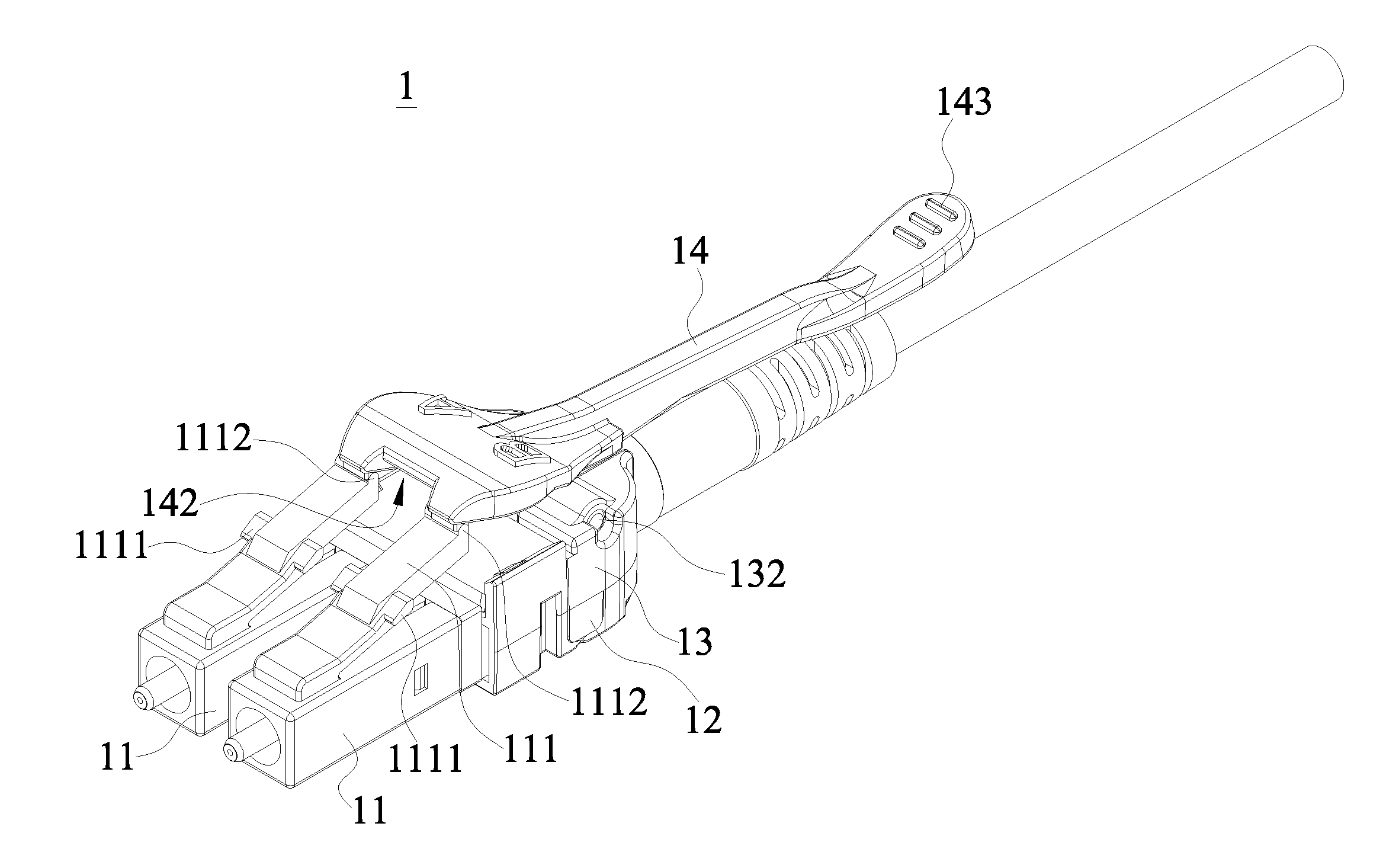
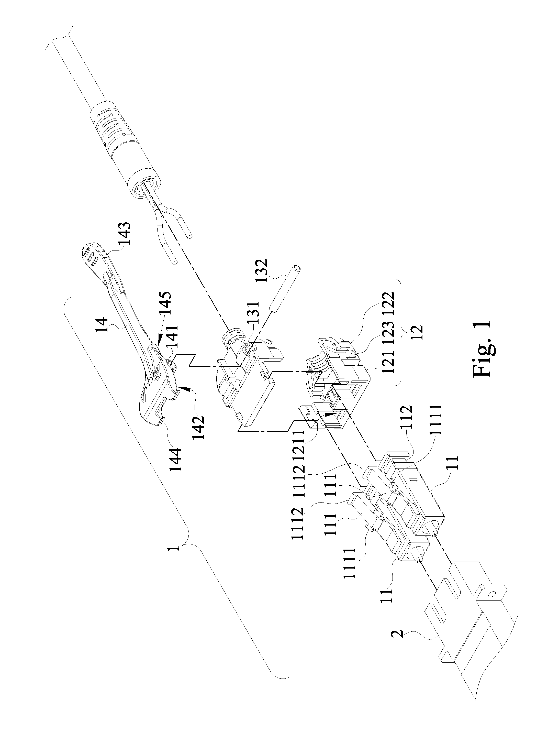
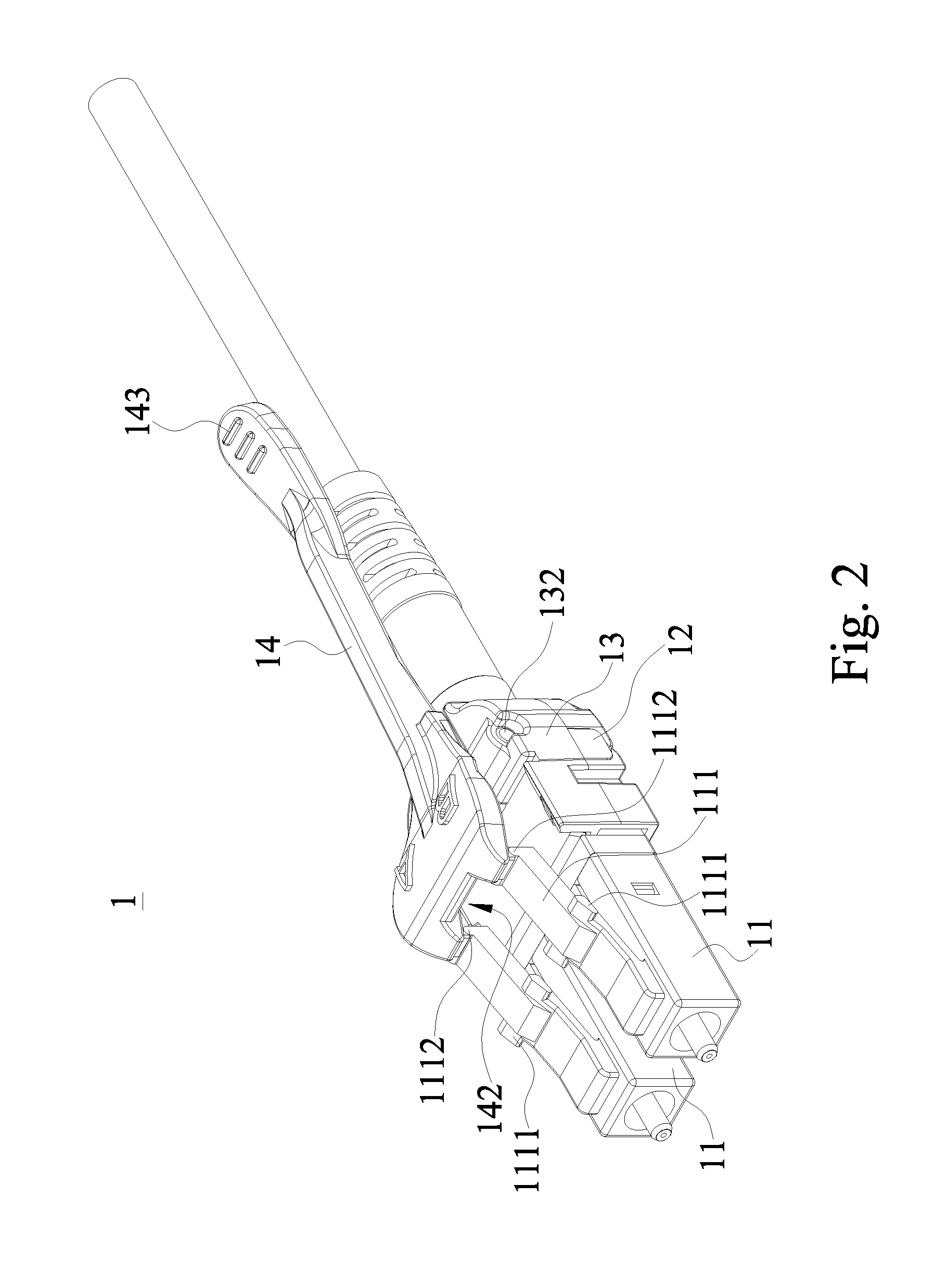
[0022]With reference to FIGS. 1 to 5 for an exploded view, a perspective view, a cross-sectional view and schematic views of a duplex fiber optic connector plug 1 in accordance with a preferred embodiment of the present invention respectively, the duplex fiber optic connector plug 1 is provided for connecting a fiber optic socket 2 to complete a signal connection, and the duplex fiber optic connector plug 1 comprises a pair of fiber optic connectors 11, a first casing 12, a second casing 13 and a release lever 14.

[0023]Each fiber optic connector 11 has a release bracket 111 installed on a surface of the fiber optic connector 11 and obliquely extended upwardly from the front end to the rear end of the fiber optic connector 11, and a locking piece 1111 disposed on both sides of the middle section of the rel...


PUM


Abstract

A duplex fiber optic connector plug includes at least one fiber optic connector, a first casing, a second casing and a release lever. The release lever is axially coupled to a surface of the first casing and has an end coupled to a release bracket of the fiber optic connector to form a seesaw design. During operation, the release lever is compressed by the force of the finger, so that an end of the release lever is elevated, and the other end compresses the release bracket downward to release from a fiber optic socket, so as to provide an intuitively convenient operation and improve the convenience of use.

Description

CROSS-REFERENCE TO RELATED APPLICATIONS[0001]This non-provisional application claims priority under 35 U.S.C. §119(a) on Patent Application No(s). 103103105 filed in Taiwan, R.O.C. on Jan. 28, 2014, the entire contents of which are hereby incorporated by reference.BACKGROUND OF THE INVENTION[0002]1. Field of the Invention[0003]The present invention relates to the technical field of fiber optic connectors, and more particularly to a duplex fiber optic connector plug operated by an upward pushing method.[0004]2. Description of the Related Art[0005]Most traditional network communication technologies utilize copper wires as network jumping to connect different machine cabinets in a network engine room and a medium for transmitting data through an electric signal transmission method. As network technology advances and data volume becomes increasingly larger, the general electric signal transmission method no longer meets application requirements, so that data are transmitted by optical s...

Claims


Application Information

Patent Timeline
Patent Type & Authority Applications(United States)
IPC IPC(8): G02B6/38
CPCG02B6/3893G02B6/3879
Inventor LIN, YEN-LIN
Owner JYH ENG TECH
Why Eureka
Try Eureka