Detachable vehicle-mounted banner assembly having improved display and mounting features

a technology of vehicle-mounted banners and banners, which is applied in the direction of machine supports, instruments, manufacturing tools, etc., can solve the problems of achieve the effects of improving durability, maintaining readability, and low durability of cloth flags

Inactive Publication Date: 2015-07-30
HARDFLAGS
View PDF9 Cites 9 Cited by
  • Summary
  • Abstract
  • Description
  • Claims
  • Application Information

AI Technical Summary

Benefits of technology

[0005]As mentioned, many conventional automobile-mounted banners comprise a cloth flag mounted to a fixed mast which flaps in the wind. The performance of the cloth flag is highly dependent on the automobile's speed (e.g., too slow and the flag is not extended and not readable; too fast and the flag flaps too frequently to read). The durability of such cloth flags is also very low. Various embodiments of the invention described herein provide a configuration that not only improves durability but also maintains readability at any travelling speed. Certain embodiments replace conventional cloth flags with a substantially rigid body configured to maintain steady alignment with an imposed airflow. Certain embodiments having the substantially rigid body concurrently improve readability, as the “hard” flag is always extended regardless of travelling speed.
[0006]According to various embodiments, a detachable vehicle-mounted banner assembly having improved display and mounting features is provided. The banner assembly comprises: a banner panel defining two opposing and at least semi-rigid surfaces, the surfaces comprising at least a leading edge; a banner mast comprising a base portion and a flanged portion, the flanged portion comprising an angled leading edge and a trailing slot, the trailing slot being configured to selectively engage at least the leading edge of the banner panel; and a base assembly having a first portion configured for attachment adjacent a surface of a vehicle and a second portion configured to attachment relative to the base portion of the banner mast. The base portion of the banner mast is elongate and has a base longitudinal axis about which the banner mast and the banner panel pivot; and the flanged portion of the banner mast extends away from the base portion, is elongate, and has a flange longitudinal axis oriented at an acute angle relative to the base longitudinal axis.
[0007]According to various embodiments, a method of mounting a detachable vehicle-mounted banner assembly having improved display and mounting features is provided. The method comprises the steps of: fixedly attaching a base assembly to a surface of the vehicle, the base assembly having a first portion configured for attachment adjacent the surface of the vehicle and a second portion configured to attachment relative to a base portion of a banner mast of the banner assembly; and selectively attaching the banner mast to the second portion of the base assembly, the banner mast comprising a base portion and a flanged portion, the flanged portion comprising an angled leading edge and a trailing slot, the trailing slot being configured to selectively engage at least a leading edge of a banner panel.

Problems solved by technology

The durability of such cloth flags is also very low.

Method used


Image

  • Detachable vehicle-mounted banner assembly having improved display and mounting features
  • Detachable vehicle-mounted banner assembly having improved display and mounting features
  • Detachable vehicle-mounted banner assembly having improved display and mounting features

Examples


first exemplary embodiment

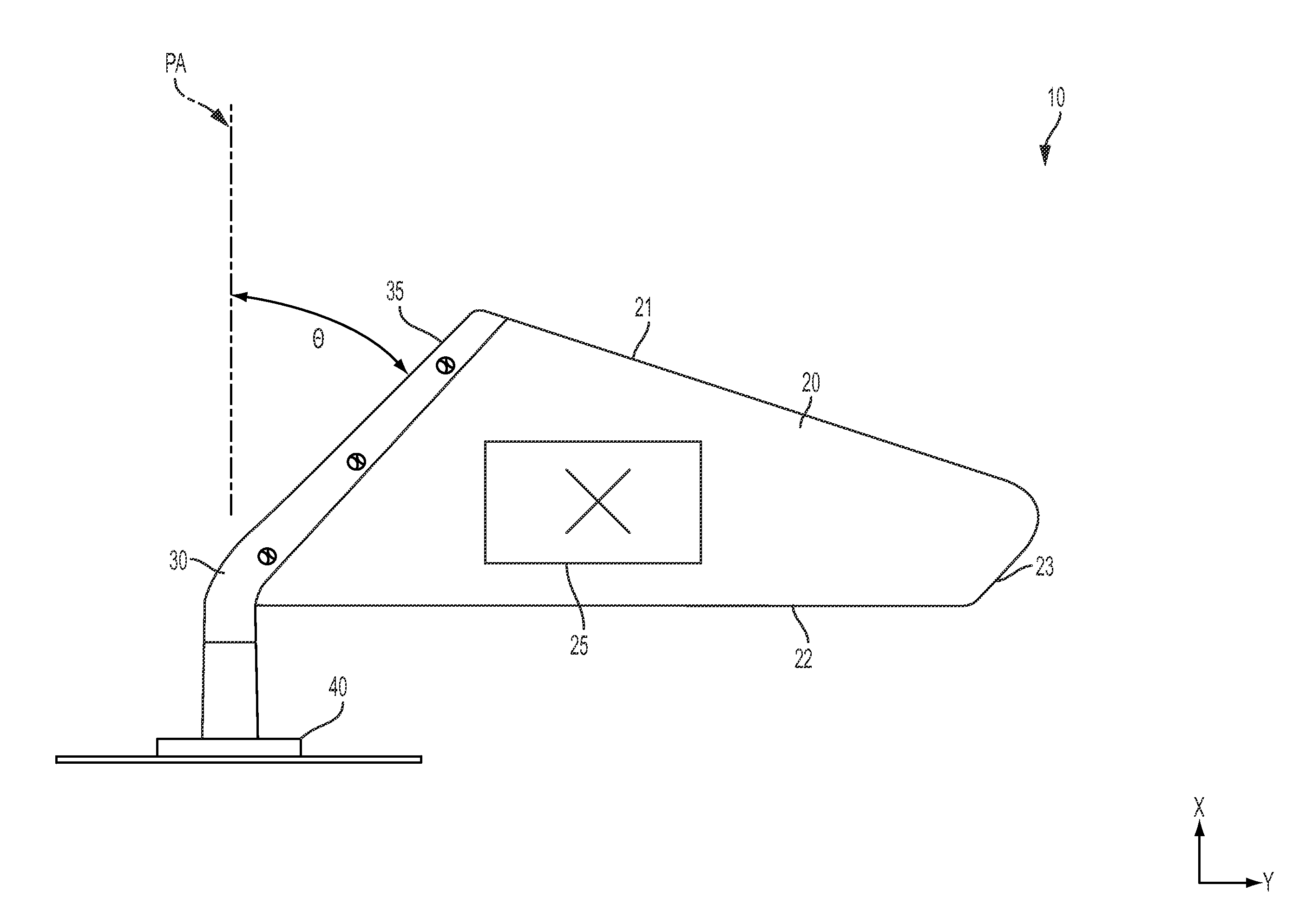
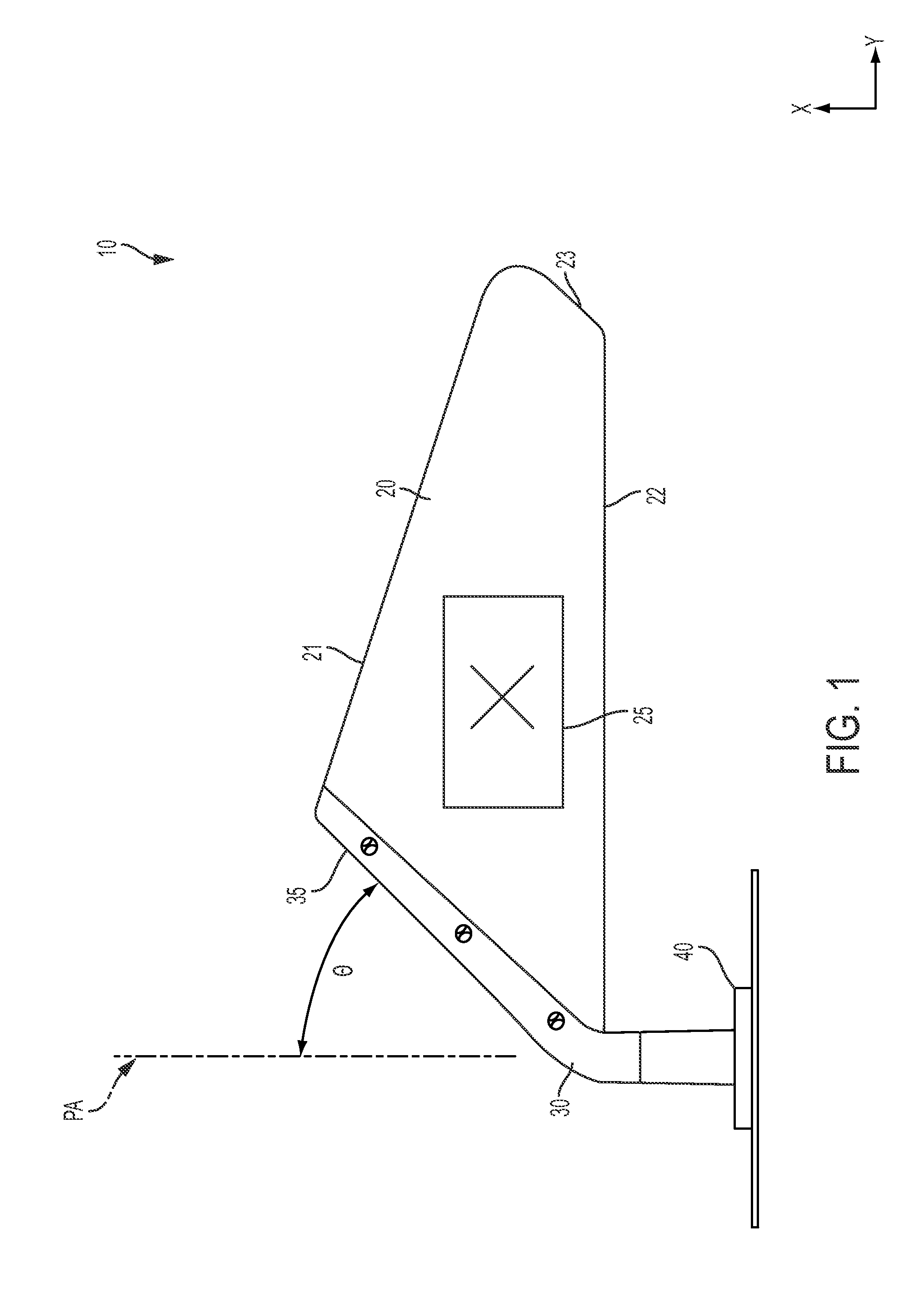
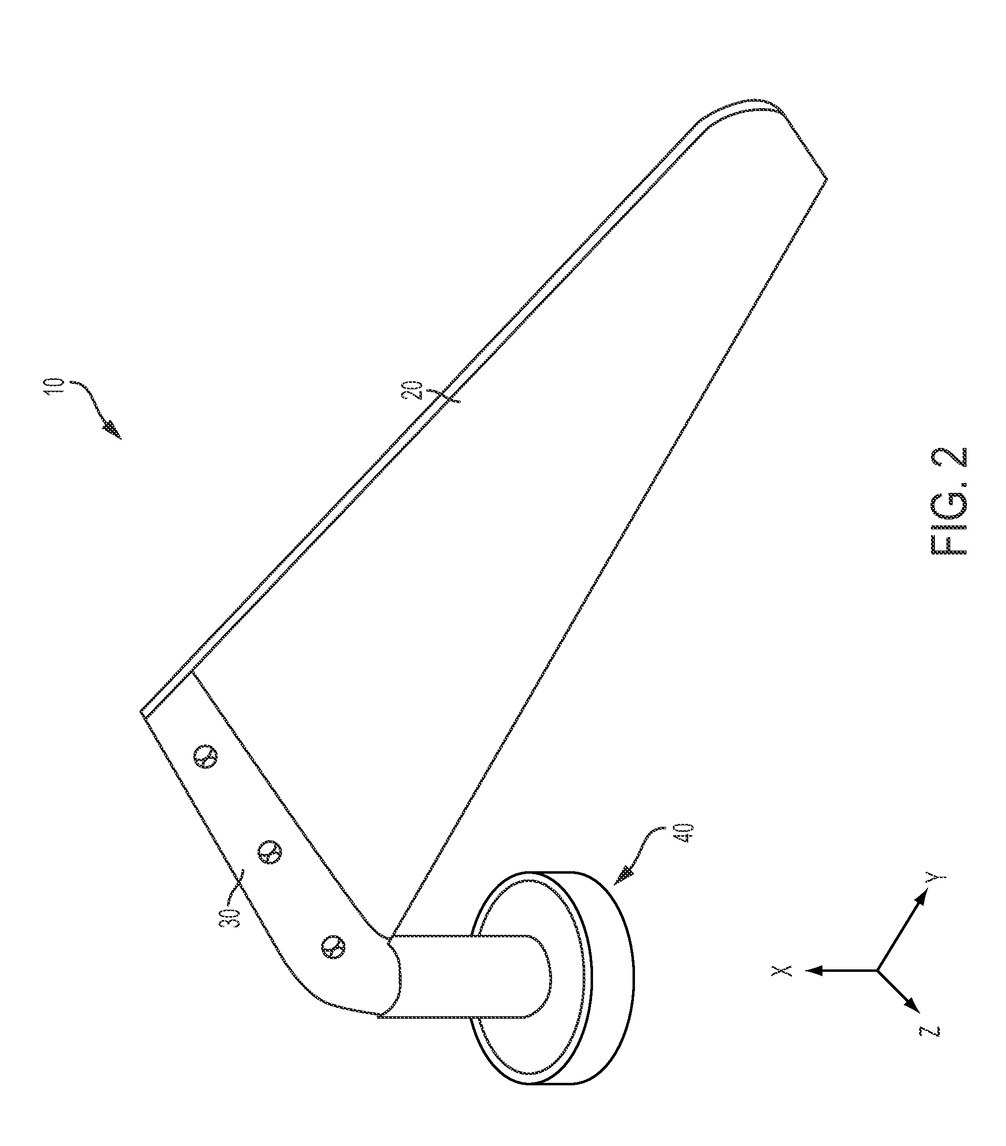
[0032]5 Vehicle Surface[0033]10 Overall Banner Assembly[0034]20 Banner panel[0035]21 Panel Upper Edge[0036]22 Panel Lower Edge[0037]23 Panel Trailing Edge[0038]24 Panel Leading Edge (exploded)[0039]25 Panel Logo (exemplary)[0040]30 Banner Mast[0041]31 banner mast base[0042]32 elongate cavity[0043]33 banner mast flange[0044]34 elongate slot[0045]35 angled leading edge[0046]40 Magnetic Base Assembly[0047]41 Post[0048]42 Magnet Subassembly[0049]43 Screw[0050]44 Protective Label[0051]45 Protective Boot[0052]50 Panel Mount Rivets (aka Plastic Binding Posts)[0053]60 Mast Retention Rivet

second exemplary embodiment

[0054]110 Overall Banner Assembly[0055]120 Banner panel[0056]130 Banner Mast[0057]131 banner mast base[0058]132 elongate cavity[0059]133 banner mast flange[0060]135 banner mast threads[0061]140 Magnetic Base Assembly[0062]141 Post[0063]142 Magnet Subassembly[0064]143 Screw[0065]145 Protective Boot[0066]146 Post Threads[0067]150 Panel Mount Rivets (aka Plastic Binding Posts)

third exemplary embodiment

[0068]205 Vehicle Surface[0069]210 Overall Banner Assembly[0070]220 Banner panel[0071]230 Banner Mast[0072]231 banner mast base[0073]233 banner mast flange[0074]240 Base Assembly[0075]241 Post[0076]242 Adapter[0077]242A Tower Portion[0078]242B Base Portion[0079]242C Recess Portion[0080]242D Central Orifice[0081]243 Screw[0082]244 Stake Hole Mount Assembly[0083]245 Top Part[0084]246 Bottom Part[0085]247 Fasteners[0086]248 Spring Portion[0087]249 Ball Portion[0088]270 Elongate Orifice[0089]272 Elongate Guard Portion[0090]275 Top Part Fastener Holes[0091]276 Bottom Part Fastener Holes[0092]280 Bottom Part Alignment Tabs[0093]250 Panel Mount Rivets (aka Plastic Binding Posts)[0094]260 Mast Retention Rivet[0095]290 Direction of Movement for Stake Hole Mount Engagement


PUM

PropertyMeasurementUnit
acute angleaaaaaaaaaa

Abstract

A detachable vehicle-mounted banner assembly is provided, comprising a banner panel defining two opposing and at least semi-rigid surfaces, the surfaces comprising at least a leading edge; a banner mast comprising a base portion and a flanged portion, the flanged portion comprising an angled leading edge and a trailing slot, the trailing slot being configured to selectively engage at least the leading edge; and a base assembly having a first portion configured for attachment to a vehicle and a second portion configured to attachment relative to the base portion. The base portion is elongate and has a base longitudinal axis about which the banner mast and the banner panel pivot; and the flanged portion of the banner mast extends away from the base portion and has a flange longitudinal axis oriented at an acute angle relative to the base longitudinal axis. A method of mounting the assembly is also provided.

Description

CROSS-REFERENCE TO RELATED APPLICATIONS[0001]This application is a continuation-in-part of U.S. patent application Ser. No. 14 / 304,450, filed Jun. 13, 2014, which claims priority to and the benefit of U.S. Provisional Patent Application Ser. No. 61 / 860,376, filed Jul. 31, 2013, the contents of both of which are hereby incorporated by reference in their entirety.BACKGROUND[0002]Many persons desire to display flags temporarily in a variety of locations for decorative purposes, as symbols of allegiance, support or affiliation, or as means for commercial advertising. As a non-limiting example, athletic team enthusiasts, such as college or high school students, their parents and relatives, as well as other team supporters, often wish to display a symbol, name, mascot, or color of their school as an expression of allegiance and support.[0003]A prime opportunity for displaying a team's symbols occurs when supporters are traveling in a vehicle (e.g., a truck, car, or the like) to and from a...

Claims


Application Information

Patent Timeline
Patent Type & Authority Applications(United States)
IPC IPC(8): G09F17/00F16M13/02
CPCG09F17/00G09F2017/0075F16M13/02Y10T29/49826
Inventor BIGHAM, SHANNON HAROLDCOVERT, LANCE NICHOLASWARD, JR., JAMES HANSFORD
Owner HARDFLAGS
Why Eureka
Try Eureka