Multiplying current conveyor for amplifier

a current conveyor and amplifier technology, applied in the direction of electric variable regulation, process and machine control, instruments, etc., can solve the problems of limited use of unity gain current conveyors, high gain across a wide bandwidth, and significant disadvantages of such typical current conveyor arrangements

Active Publication Date: 2015-07-30
SNAPTRACK
View PDF1 Cites 6 Cited by
  • Summary
  • Abstract
  • Description
  • Claims
  • Application Information

AI Technical Summary

Benefits of technology

[0019]The apparatus may comprise a differential amplifier provided to receive the source voltages of the first and second transistors and regulate the source vol...

Problems solved by technology

Current conveyors are used in high frequency applications where a conventional operational amplifier cannot be used because the conventional design is limited by gain-bandwidth products.
In an amplifier where high gain across a wide bandwidth is advantageous, the usefulness of the unity gain current conveyor is limited.
The unit...

Method used


Image

  • Multiplying current conveyor for amplifier
  • Multiplying current conveyor for amplifier
  • Multiplying current conveyor for amplifier

Examples


Embodiment Construction

[0028]The present invention is now described by way of reference to preferred examples and preferred implementations.

[0029]However one skilled in the art will appreciate that the present invention is not limited to its application to the specific examples as set out herein below.

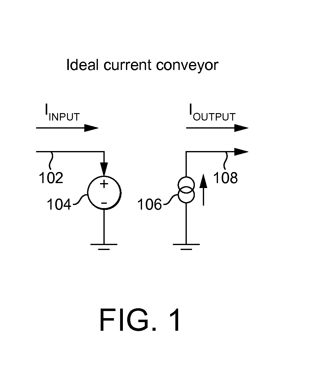
[0030]The present invention is described herein by way of a circuit termed a current conveyor. However in general there is provided a circuit, which may be termed a controlled current source or may be termed a current conveyor. The term current conveyor is a term which is used in the art to describe a circuit having the functionality of current conveying as described herein, and may be also referred to as a controlled current source.

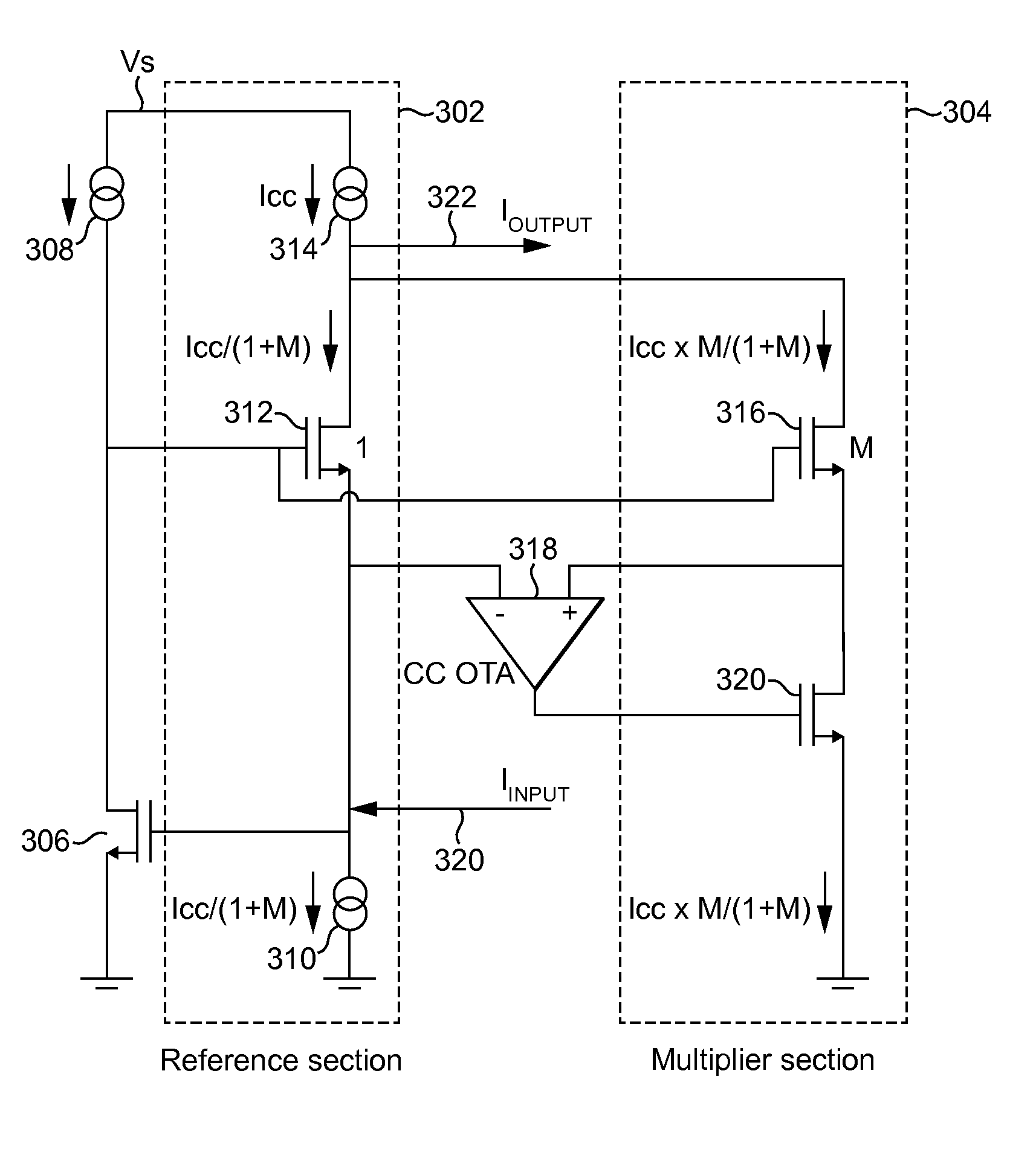
[0031]With reference to FIG. 3, there is illustrated a multiplying current conveyor in accordance with a preferred implementation.

[0032]The multiplying current conveyor includes a reference section 302 and a multiplier section 304.

[0033]The multiplying current conveyor comprises ...


PUM


Abstract

A circuit having a first transistor being a common gate connected transistor and a second transistor, the second transistor being M times the size of the first transistor, the first and second transistors having commonly connected gates and commonly connected drains, wherein an apparatus is provided to regulate the source voltage of the second transistor to track the source voltage of the first transistor, wherein the current gain of the circuit is M+1.

Description

CROSS-REFERENCE TO RELATED APPLICATION[0001]Great Britain Patent Application No. 1401215.7, with a filing date of Jan. 24, 2014, is incorporated herein by reference in its entirety.FIELD OF THE INVENTION[0002]The present invention relates to a current conveyor for providing a conduit for a signal current from a current source to a load. Such a current conveyor may be advantageously utilised in an amplification stage of an envelope tracking power amplifier system.BACKGROUND OF THE INVENTION[0003]Envelope tracking power amplifier systems are known in the art, and generally comprise the provision of an input signal to be amplified on an RF input path to a signal input of a power amplifier, and an envelope path for generating a modulated power supply based on the envelope of the input signal, with the modulated power supply being provided to a power supply input of the power amplifier.[0004]In applications envelope tracking power amplifier systems are desired to be highly efficient. In ...

Claims


Application Information

Patent Timeline
IPC IPC(8): H03F1/02H03F3/45
CPCH03F1/0211H03F2200/129H03F2203/45268H03F3/45071H03F1/0222H03F3/193H03F3/24H03F3/345H03F2200/456H03F2200/91H03F3/347
Inventor FAGG, RUSSELL
Owner SNAPTRACK
Why Eureka
Try Eureka