Mobile Renewable Energy Light Tower

a renewable energy and light tower technology, applied in the field of portable renewable energy light towers, can solve the problems of increasing the cost of using lights, producing unwanted noise and pollution, and needing temporary or emergency electrical power, and achieves the effects of convenient loading and unloading, increased safety and stability, and convenient driving

Inactive Publication Date: 2015-07-30
SIRIUS LIGHT TOWERS LLC
View PDF7 Cites 17 Cited by
  • Summary
  • Abstract
  • Description
  • Claims
  • Application Information

AI Technical Summary

Benefits of technology

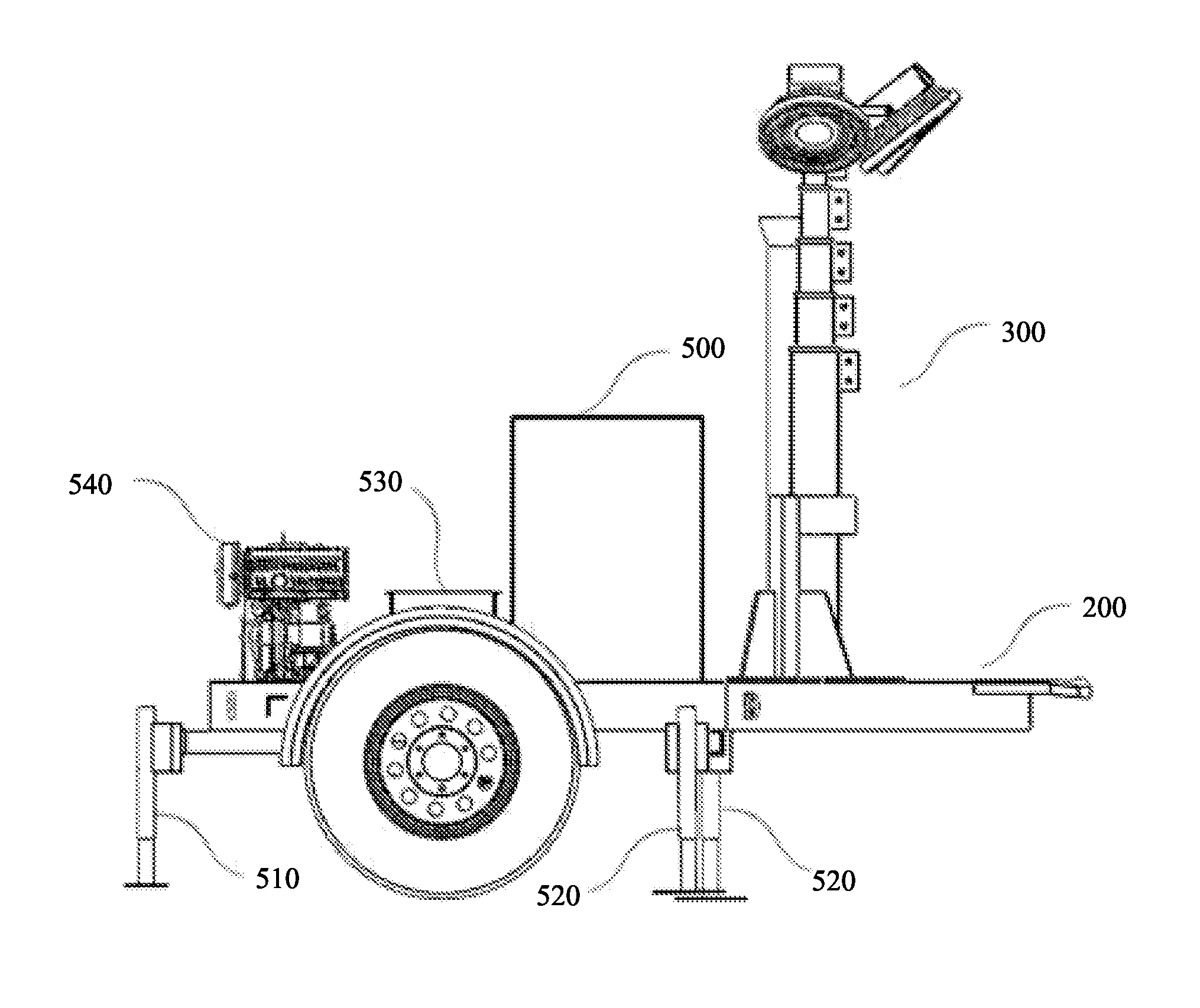
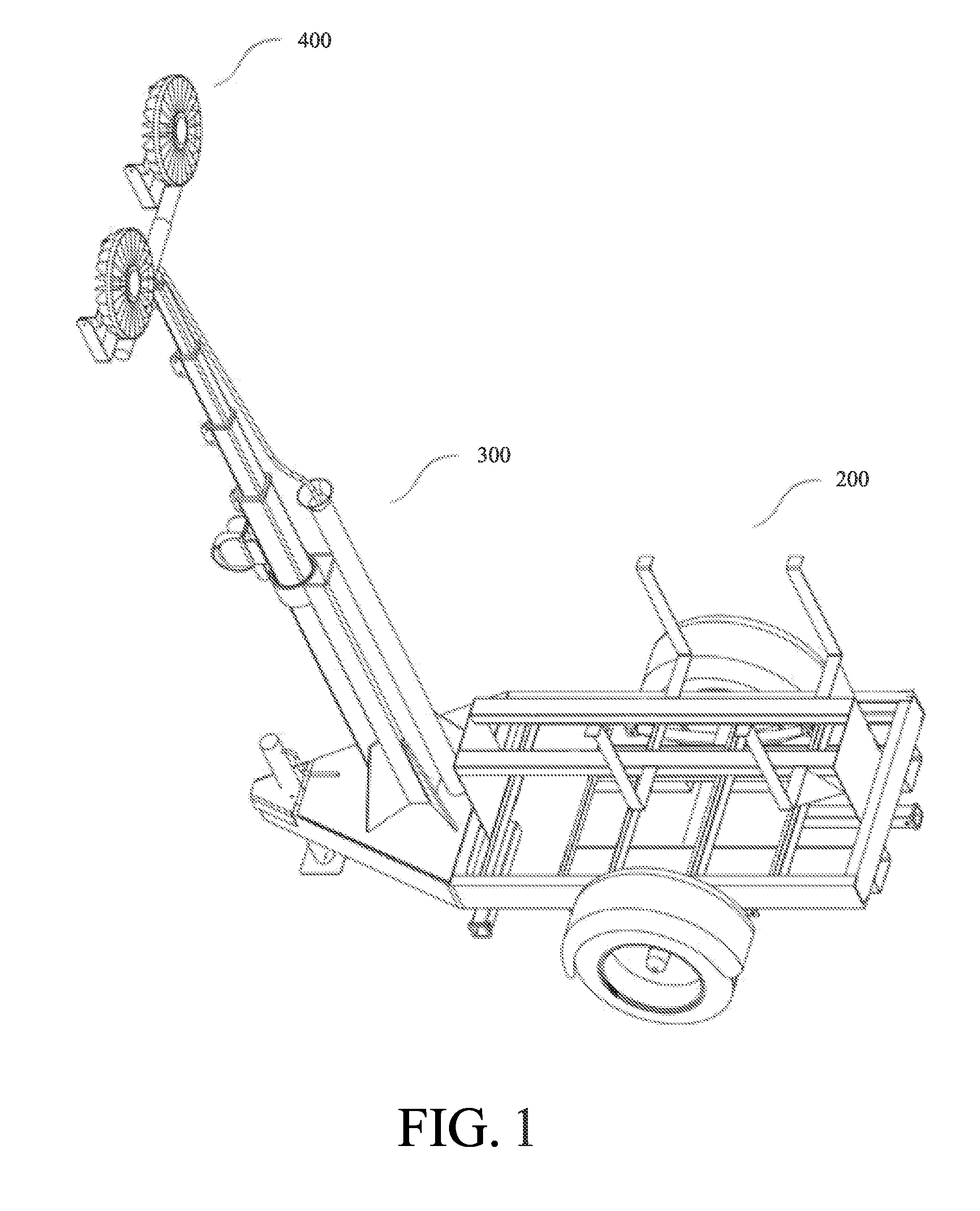
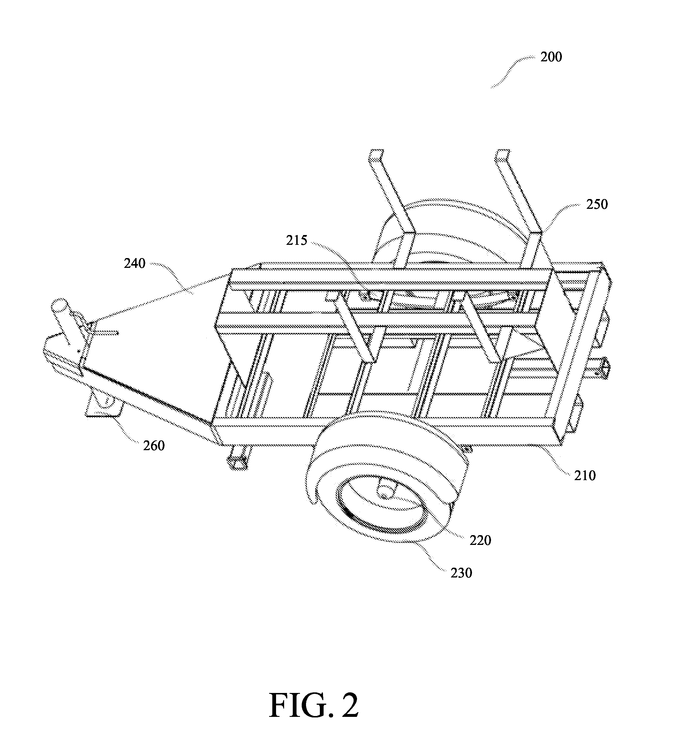
[0012]The frame component can comprise a trailer which can include a frame, an axle coupled to the frame, wheels coupled to the axle, a hitch coupled to a front end of the frame, and a stand for supporting the trailer frame when the MRE Light Tower is not being towed. The front end of the frame can comprise a flat surface upon which to mount a mast component; the remainder of the trailer frame can comprise a bed comprised of steel tubing in a rectangular configuration with supporting cross members. In one embodiment of the present invention, the remainder of the trailer can is constructed of a steel base with perimeter walls protruding upwards, constituting a secondary containment for all components containing effluents wherein the bed thereby contains any effluents that may leak out from any of the other components, thereby protecting the environment from potential contamination. In one embodiment of the present invention, the frame component has forklift receptacles on each side, enabling the unit to be easily loaded and unloaded from the side of a flatbed truck. In an embodiment, the axle can be a 6,000 lb. axle that is cut down and configured to fit about a 5.2 foot trailer width. In an embodiment, the hitch is a standard pintle hitch for ease of towing.
[0013]In an embodiment, the power management component and battery system can be mounted on the bed, providing additional safety and stability for the MRE Light Tower. As the battery system is primarily comprised of batteries and which comprise a substantial portion of the weight of the device, mounting the battery system on the bed provides the lowest practical center of gravity.
[0014]In an embodiment, the structure component can also include a cover coupled to the top of the frame comprising the bed to protect a power management component and battery system. In an embodiment, the cover can also protect a fuel component. In an embodiment, brackets can be attached to both sides of the frame such that a fuel component can be mounted and supported a safe distance above the battery system mounted on the bed. In an embodiment, brackets can be attached to the top of the cover to support a solar component. In an embodiment, the cover is provided with ventilation for the enclosed power management component. In an embodiment, the cover is provided with ventilation for an enclosed fuel component.
[0015]The MRE Light Tower can be fabricated to any dimensions. In an embodiment, the MRE Light Tower should be easily driven on public roads and the trailer should fit within standard traffic lanes. The width may be about 5 feet to 8.5 feet which is the maximum legal width for most U.S. highways. In an embodiment, the width is 5.2 feet, which allows maximum efficiency in transporting the MRE Light Towers on trucks. The length of the MRE Light Tower can be about 10 to 20 feet in length. In an embodiment, the length of the MRE Light Tower is 10.5 feet, which allows maximum efficiency in transporting the MRE Light Towers on trucks. The frame component can be made of steel tubing which can have circular, square or rectangular cross sections. For example, the frame may be made of 2″×3″ or 3″×3″ steel tube.

Problems solved by technology

However, in some applications, temporary or emergency electrical power may be needed.
With the volatility of oil prices, diesel is, at times, very expensive, causing the cost of using the lights to increase substantially.
Tower lights are generally diesel powered, producing unwanted noise and pollution.
Solar powered tower lights tend to be unwieldy in terms of size and shape.
Light components are generally supported by masts which are folded horizontally flat on the structure component, a configuration which tends to damage the solar panels.

Method used


Image

  • Mobile Renewable Energy Light Tower
  • Mobile Renewable Energy Light Tower
  • Mobile Renewable Energy Light Tower

Examples


Embodiment Construction

[0051]Before the invention is described in further detail, it is to be understood that the invention is not limited to the particular embodiments described, as such may, of course, vary. It is also to be understood that the terminology used herein is for the purpose of describing particular embodiments only, and not intended to be limiting, since the scope of the present invention will be limited only by the appended claims.

[0052]Where a range of values is provided, it is understood that each intervening value, to the tenth of the unit of the lower limit unless the context clearly dictates otherwise, between the upper and lower limit of that range and any other stated or intervening value in that stated range is encompassed with the invention. The upper and lower limits of these smaller ranges may independently be included in the smaller ranges is also encompassed within the invention, subject to any specifically excluded limit in the stated range. Where the stated range includes on...


PUM


Abstract

The present invention is directed to a mobile light tower that utilizes multiple sources of energy to provide a highly energy efficient source of illumination. The lights of the light tower draw power from the energy stored in the batteries. During the day, solar energy can captured and stored in batteries. In times of cloud cover, or at night, wind energy can be captured and stored in the batteries. Additional alternative energy sources can also be incorporated. In the event that neither of these sources are sufficient, a fuel powered generator can be utilized to generate energy to be stored in the batteries.

Description

CROSS-REFERENCE TO RELATED APPLICATIONS[0001]The present application claims the benefit of U.S. Provisional Application No. 61 / 933,326 filed on Jan. 30, 2014, incorporated by reference herein and for which benefit of the priority date is hereby claimed.FEDERALLY SPONSORED RESEARCH[0002]Not applicable.SEQUENCE LISTING OR PROGRAM[0003]Not applicable.FIELD OF INVENTION[0004]The present invention relates to the field of portable lighting systems and devices. More specifically, the invention is directed to the field of portable lighting systems and devices utilizing multiple sources of power.BACKGROUND OF THE INVENTION[0005]A solar power system uses one or more solar panels to convert sunlight into electricity. Solar power systems consist of multiple components, including the photovoltaic modules, mechanical and electrical connections and mountings and means of regulating or modifying the electrical output. A wind power system uses one or more wind turbines to convert wind into electrici...

Claims


Application Information

Patent Timeline
Patent Type & Authority Applications(United States)
IPC IPC(8): H04N7/18F21L4/02F21V21/06F21S9/04F21S9/03F21L4/08F21L13/00
CPCH04N7/183F21L4/08F21L4/02F21W2131/10F21S9/043F21S9/037F21V21/06F21L13/00F21S9/04F21V21/22Y02B20/72
Inventor CARPOFF, JEFF
Owner SIRIUS LIGHT TOWERS LLC
Why Eureka
Try Eureka