Electric wick and heater for portable vaporizer

a portable vaporizer and electric wick technology, applied in the field of electric wicks, can solve the problems of discharging more energy to reach the desired temperature, and achieve the effect of minimizing the combustion of the wick and a larger surface area

Active Publication Date: 2015-08-06
WAKALOPULOS GEORGE
View PDF5 Cites 87 Cited by
  • Summary
  • Abstract
  • Description
  • Claims
  • Application Information

AI Technical Summary

Benefits of technology

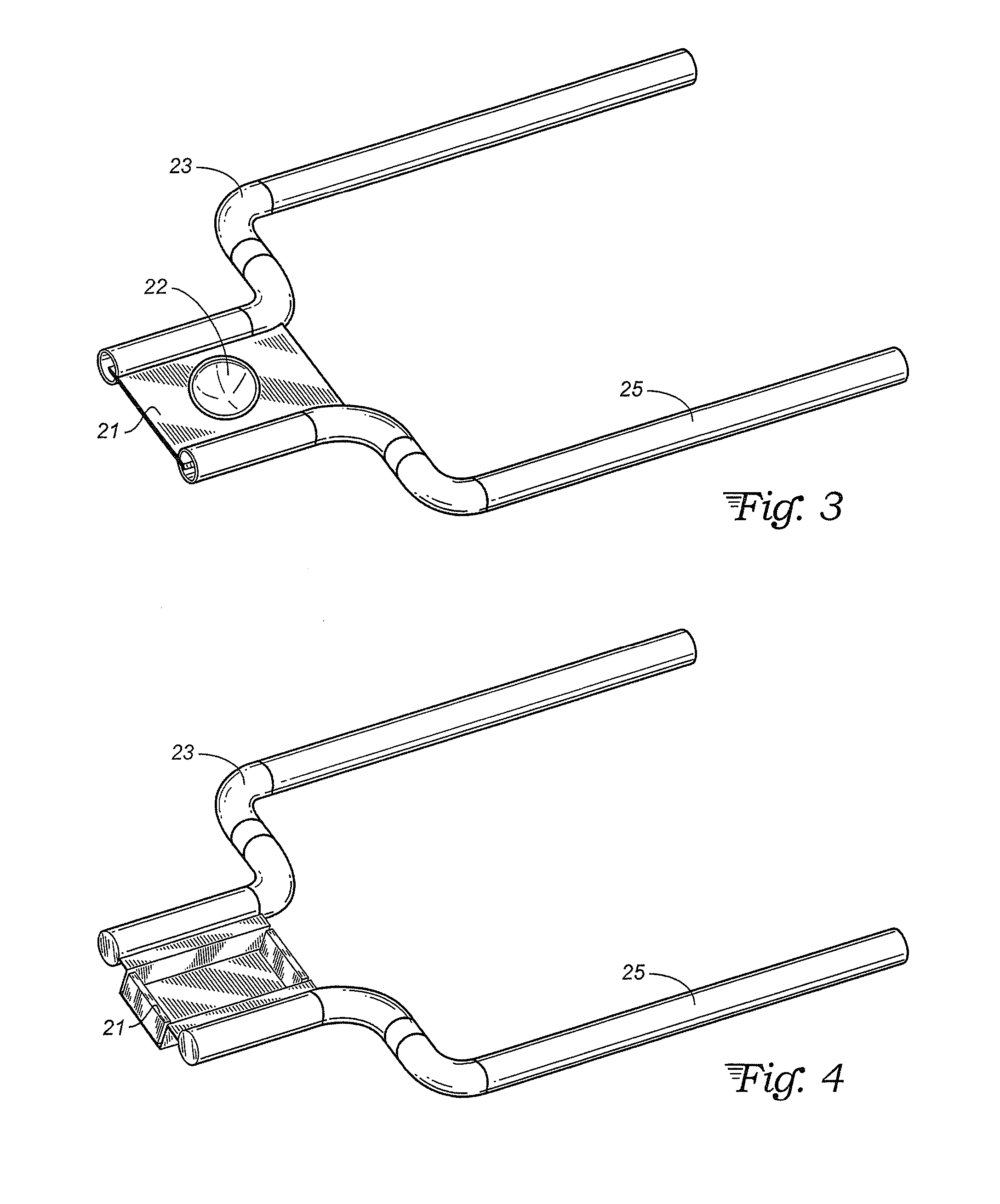
[0006]The present invention utilizes thin resistive foils instead of wires or wire meshes, to vaporize the wax, liquid, or solid materials to be vaporized in an inhaler. Due to the larger surface area of the foils, they can vaporize equal amounts of material, per unit power, with a lower temperature, and thus minimizing the combustion of the wick, when the liquid material is depleted.
[0008]In contrast, if the heating element is also the container or wick of the vaporizable material, and also if the heating element has ultra low mass, the energy required to reach the desired temperature is minimized and thus portable vaporization devices can be made which are powered by batteries. Another advantage of ultra low mass heaters is virtually instant on off heating capability which allows for precise temperature control which is essential to extract only the low temperature vapor, and not burn the material, which causes harmful or carcinogenic gases to be generated.
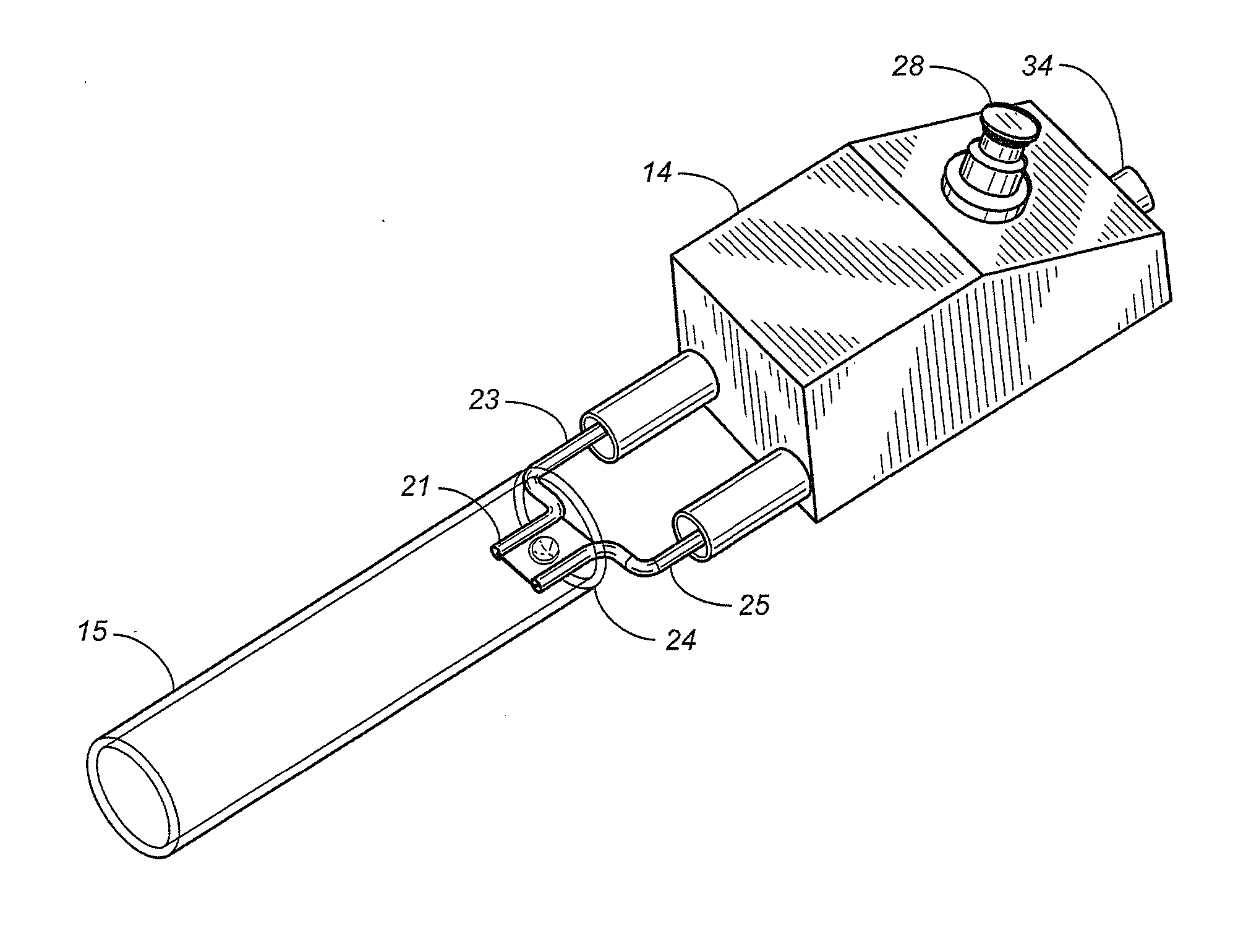
[0009]In another embodiment of the invention, by spiraling or folding the resistive foil material, capillary passages formed by the thin foil are maintained in communication with a vaporizable liquid. The liquid media is transported to the heating element surface, where it is vaporized, by capillary action without a wick, thus eliminating the combustion of the organic wick material. In this design, however, the surface of the foil material must be oxidized, to form an insulating barrier, to keep the contacting metal layer from shorting out between each other.

Problems solved by technology

These heating methods dissipate more energy to reach the desired temperature for vaporization due the requirement of elevating the temperature of the container which contains the material to be vaporized.

Method used


Image

  • Electric wick and heater for portable vaporizer
  • Electric wick and heater for portable vaporizer
  • Electric wick and heater for portable vaporizer

Examples


Embodiment Construction

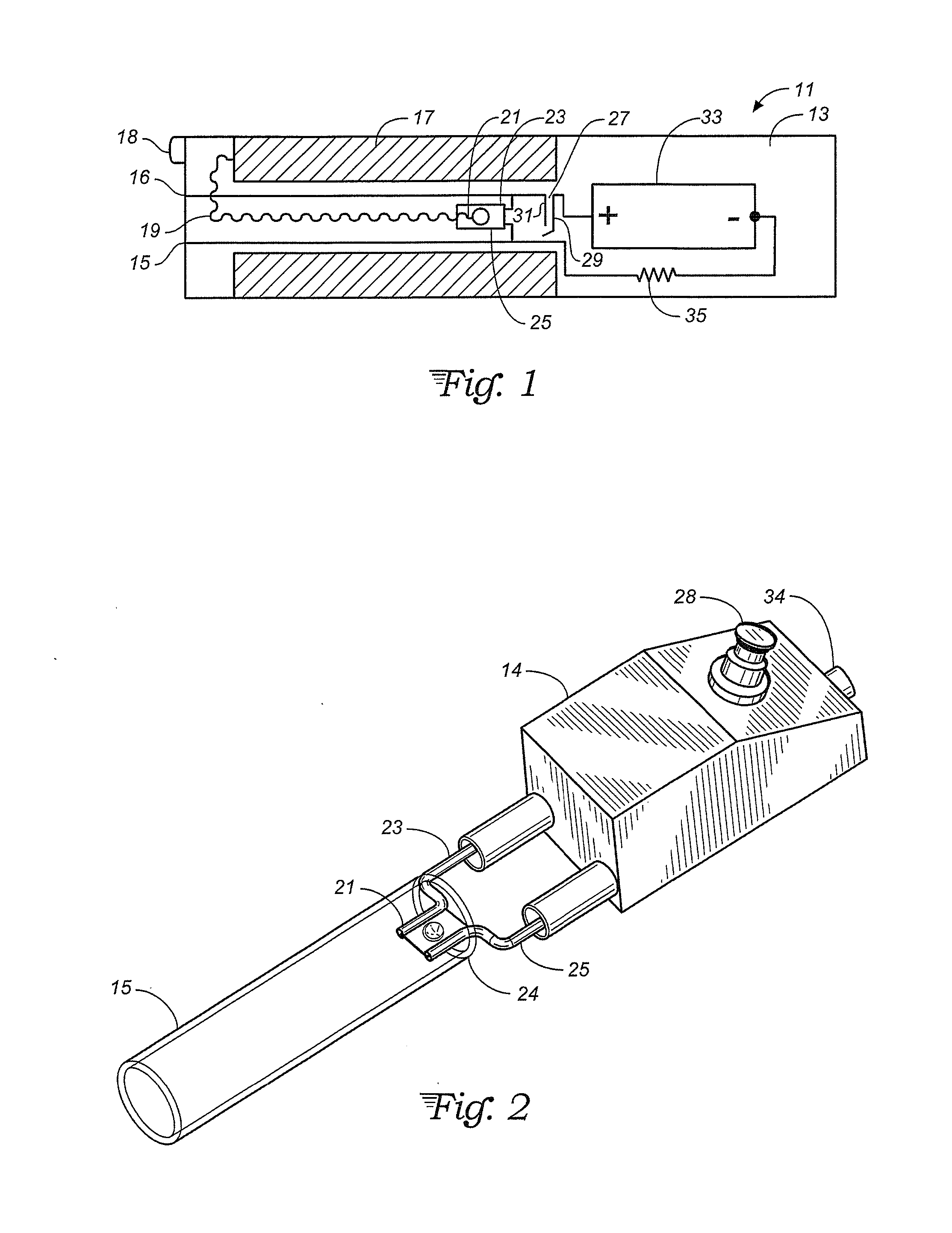
[0020]With reference to FIG. 1, a vaporizer 11 is shown having a housing 13 that has a common cigarette form factor, and would be useful as a medicinal inhaler or an electronic cigarette. The housing 13 is cylindrical with a central axis of symmetry. The housing may be plastic or glass. Within the housing, a coaxial inhalation tube 15 extends proximately 60 percent of the length of the housing. The inhalation tube has an end 16 in common with the end 18 of housing 13 intended to be near the lips of the user.

[0021]Within the housing 13, but spaced from housing end 18 is a fluid reservoir 17 which is coaxial with housing 13. Reservoir 17 may be semi-rigid sponge material that holds a supply of inhalation material, usually a fluid, such as propylene glycol, that can flow within the reservoir material in response to pressure drops. A pressure drop is established by a capillary tube 19 that extends into the reservoir material near housing end 18 and extends from the reservoir along the a...


PUM


Abstract

A resistive foil heater for a portable inhaler. A reservoir of vapor material, usually a fluid, has transport by the foil to directly heat the material to a temperature sufficient to vaporize the material to the gas phase. The foil may have a dimpled plate shape, or box shape, a capillary or parallel plate shape.

Description

CROSS-REFERENCE TO RELATED APPLICATION[0001]This application claims priority from U.S. provisional application Ser. No. 61 / 935,644, filed Feb. 4, 2014.TECHNICAL FIELD[0002]The invention relates to an electrical vaporizer for an electronic cigarette or medicinal inhaler.BACKGROUND ART[0003]The wick has been used for thousands of years to provide lighting in darkness and has progressed in the past several centuries in kerosene lamps and candles. The operation of a wick, in its basic form, utilizes capillary action, in which a liquid is transported inside a small diameter passage, by attractive forces between the passage material and the liquid properties. For example, if a small diameter glass tube is inserted into a water container, the water will rise inside the tube, to a height which is proportional to the difference in surface tension, of the glass and water, and inversely proportional to the tube diameter and the liquids' viscosity. Capillary action is one of the fundamental pro...

Claims


Application Information

Patent Timeline
Patent Type & Authority Applications(United States)
IPC IPC(8): A61M15/06H05B1/02A24F47/00A61M16/10A24F40/10A24F40/44A24F40/46
CPCA61M15/06A61M16/109A61M2205/8206A24F47/008A61M2205/36H05B1/0244A61M2205/3653A61M11/044A24F40/46A24F40/10A24F40/44
Inventor WAKALOPULOS, GEORGE
Owner WAKALOPULOS GEORGE
Why Eureka
Try Eureka