Vehicle lifting and parallel parking aid

Active Publication Date: 2015-08-06
INNOVATIVE INVENTIONS
View PDF17 Cites 5 Cited by
  • Summary
  • Abstract
  • Description
  • Claims
  • Application Information

AI Technical Summary

Benefits of technology

[0016]A vehicle lifting and parking aid system having a sidewinder wheel unit mounted between the brakes and the spindle of each wheel of a vehicle controlled from a control module located within the vehicle is disclosed. Each sidewinder wheel unit is comprised of a touch-down wheel, sidewinder wheel, DC electric high torque motor, a positioning system (motor driven rotating gears and lift gears), and a solenoid operated locking pin. In general, the device rotates between a storage position and a deployed position. In the storage position, the device is positioned under the vehicle so that it does not impair normal operation of the vehicle. When deployed, the device rotates about the axle or spindle until a touch-down wheel, aligned with the longitudinal centerline of the vehicle, lifts the primary wheels of the vehicle about one half inch off of the ground surface. Thereafter, the device is locked into place by the solenoid operated locking pin. Once

Problems solved by technology

Parallel parking allows a vehicle to park in a smaller space than with side-by-side parking, which is common in many public parking facilities, but often equally as challenging because of the action of other drivers.
Such a system must be built into the vehicle during manufacturing, thereby increasing the cost of the vehicle.
These parallel-parking systems can be expensive due to the cost of the multiple sensors and the controller touch-down that processes the algorithms.
In addition, the system implementation requires the additional cost of controllable steering (i.e. electric power steering), controllable brakes, and controllable throttles.
Some car owners choose to cut the manufacturers' coil suspension springs instead, but this method can cause the springs to weaken and even fail, resulting in an uneven or dangerous ride.
This practice can eventually cost more because it may throw off a car's alignment, resulting in wear and tear on supporting parts like the frame, tires and undercarriage.
Overall, the lifting and lowering of a vehicle can be very expensive, especially for the vehicle owner not interested in the a

Method used


Image

  • Vehicle lifting and parallel parking aid
  • Vehicle lifting and parallel parking aid
  • Vehicle lifting and parallel parking aid

Examples


Embodiment Construction

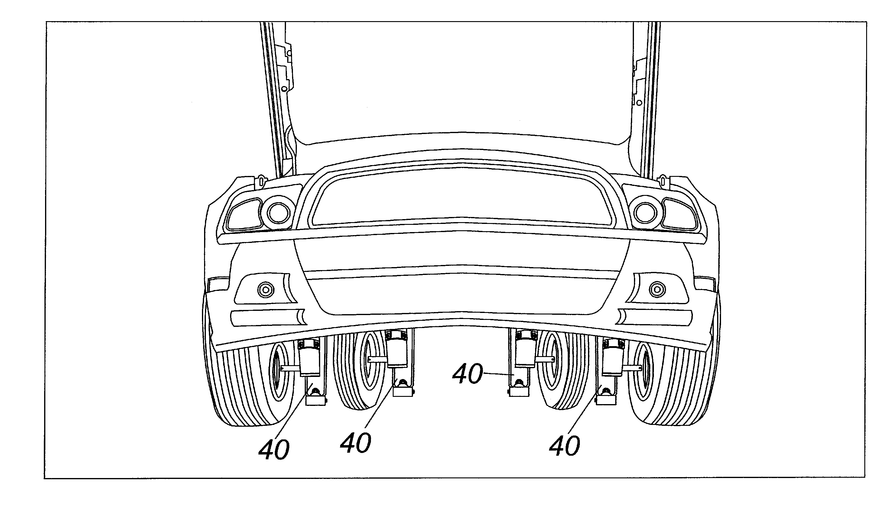
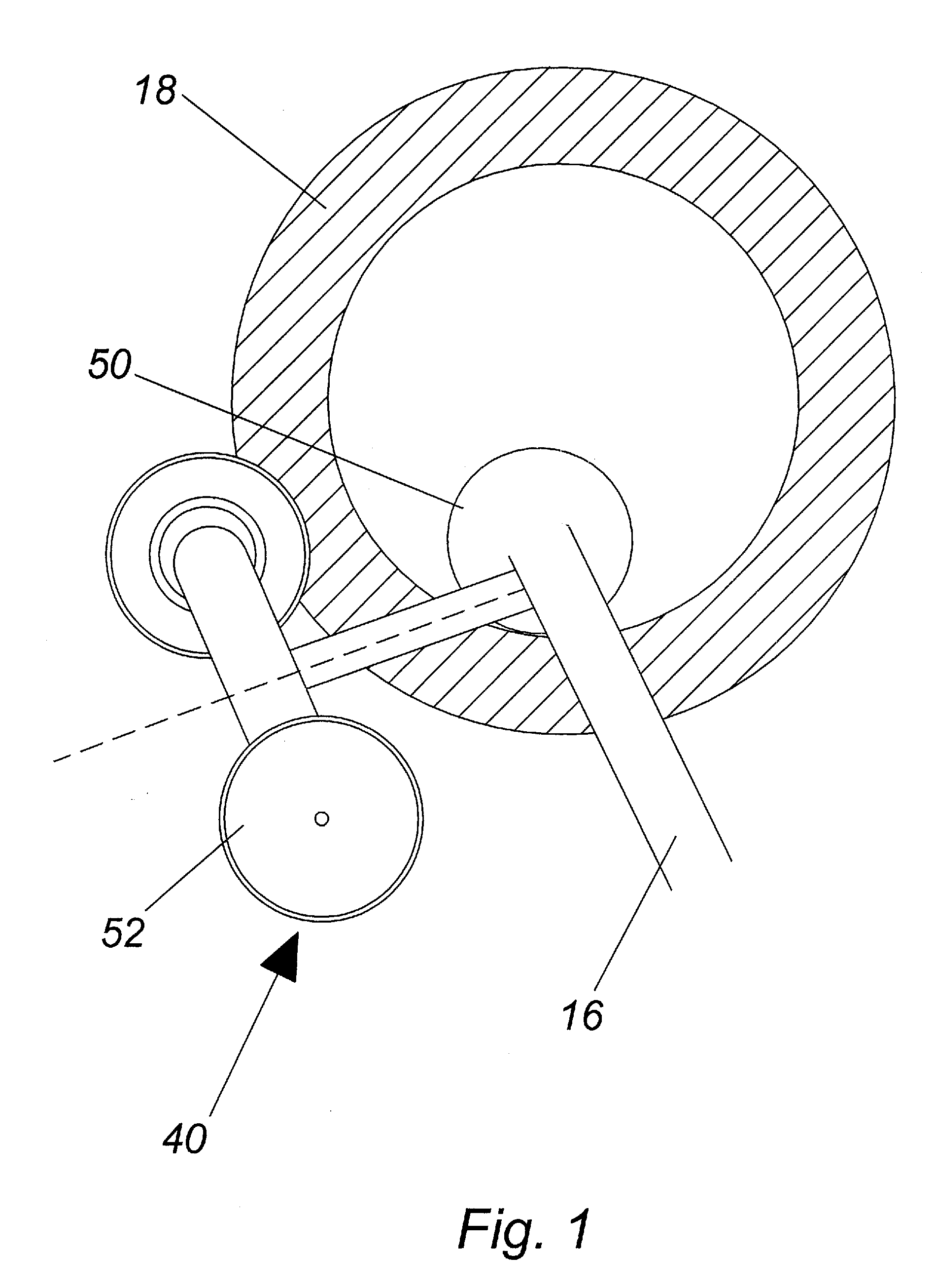
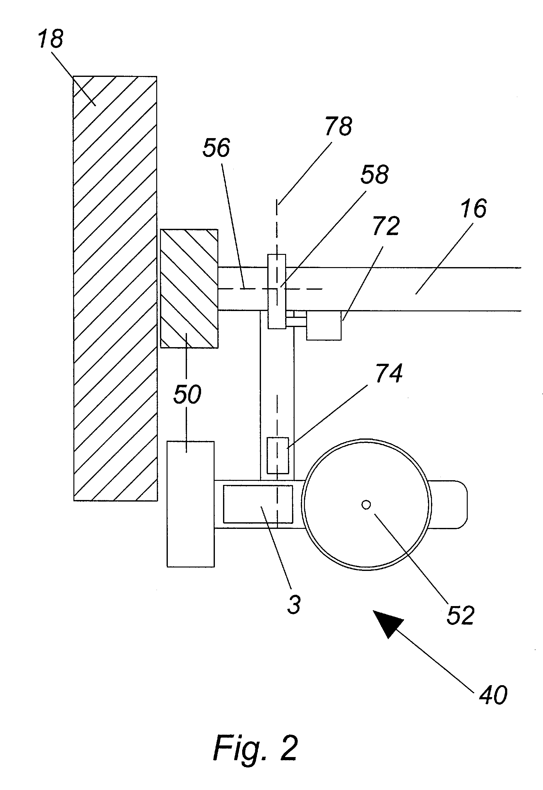
[0037]As shown in FIGS. 1-11, each sidewinder unit 40 includes a sidewinder wheel 52, a touch-down wheel 50, a high torque electric DC motor 3 which may include a gear drive 4, a first solenoid 72 for locking in the retracted and engaged positions of the sidewinder unit, and a second solenoid 74 to move the high torque electric DC motor 3 between the gearing system (from a lifting gear train to a rotating gear train). The four sidewinder units 40 are contemplated to weigh no more than 250 to 300 lbs. depending on the size and demands of each vehicle. The sidewinder unit is powered by external batteries 60, 62 (FIGS. 4 and 5), and coupled to a control module 100 (FIG. 6) located inside of the vehicle. It is contemplated that the external batteries 60, 62 be stored in the trunk of the vehicle. Each sidewinder unit 40 contains its own gearing systems 4, 5. The gearing system is comprised of motor driven rotating gears 4 and lifting gears 5 (don't see on a FIG). The motor driven rotatin...


PUM


Abstract

A vehicle lifting and parking aid system having sidewinder wheel units mounted on the axles between the brakes and the spindle of each wheel of a vehicle controlled from a control module located within the vehicle is disclosed. In the deployed position, each sidewinder unit is against the ground surface and lifts the vehicle approximately 0.5″ off the ground. Using joysticks on a control module located within the vehicle, the user is able to operate, i.e. direct, the sidewinders to the left or right at different variations in speed whereby the vehicle is moved to the left or right by way of a rotating gear train.

Description

PRIORITY CLAIM[0001]In accordance with 37 C.F.R. 1.76, a claim of priority is included in an Application Data Sheet filed concurrently herewith. Accordingly, the present invention application claims priority to U.S. Provisional Application No. 61 / 936,224, entitled “Vehicle Lifting and Parallel Parking Aid” filed Feb. 5, 2014, the contents of which are incorporated herein in their entirety.FIELD OF THE INVENTION[0002]This invention relates generally to the field of automotive accessories, and in particular to a vehicle lifting and parallel parking aid.BACKGROUND OF THE INVENTION[0003]Parallel parking, considered to be one of the most challenging maneuvers for new drivers to learn, is a method of parking a vehicle in line with other parked vehicles. Parallel parking requires driving the vehicle slightly past the parking space, parallel to the vehicle parked in front of that space and then, while maintaining a safe distance, reversing into the chosen space. Subsequent position adjustme...

Claims


Application Information

Patent Timeline
IPC IPC(8): B60S9/215B60C23/00
CPCB60S9/215B60C23/006B61B1/00B60S9/21B60S9/14B60S9/18B60K17/34
Inventor MISTROT, DON A.DUFFIELD, RICHARD P.
Owner INNOVATIVE INVENTIONS
Why Eureka
Try Eureka