Power factor measurement device

a technology of power factor and measurement device, which is applied in the direction of electric devices, instruments, transportation and packaging, etc., can solve the problems of complicated calculations of reactive power, and achieve the effects of less measurement energy consumption, easy installation, and saving power

Active Publication Date: 2015-08-06
OSAKA CITY UNIVERSITY
View PDF2 Cites 3 Cited by
  • Summary
  • Abstract
  • Description
  • Claims
  • Application Information

AI Technical Summary

Benefits of technology

[0020]The power factor measurement apparatus according to the present invention can directly measure a power factor in detail in an inductive motor by effectively using the advantages of a magnetic thin film power sensor such as non-contact (principle), easy installation (ultracompact and thin) and saved power (less consumed energy on measurement). Therefore, it becomes possible to visualize a power consuming situation, and by applying the present invention to a circuit having a reactance component such as inductive motor, thereby controlling power saving drive depending on an operation situation or load situation.

Problems solved by technology

However, the method has a problem that calculations of reactive power are complicated during a load variation.

Method used


Image

  • Power factor measurement device
  • Power factor measurement device
  • Power factor measurement device

Examples


first embodiment

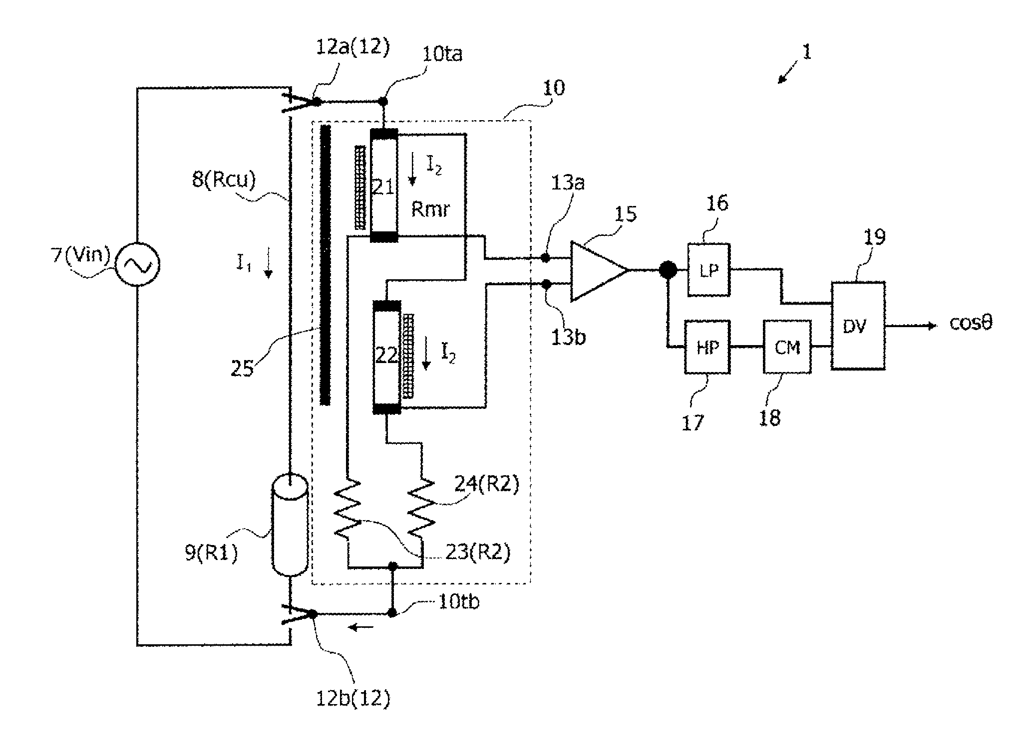
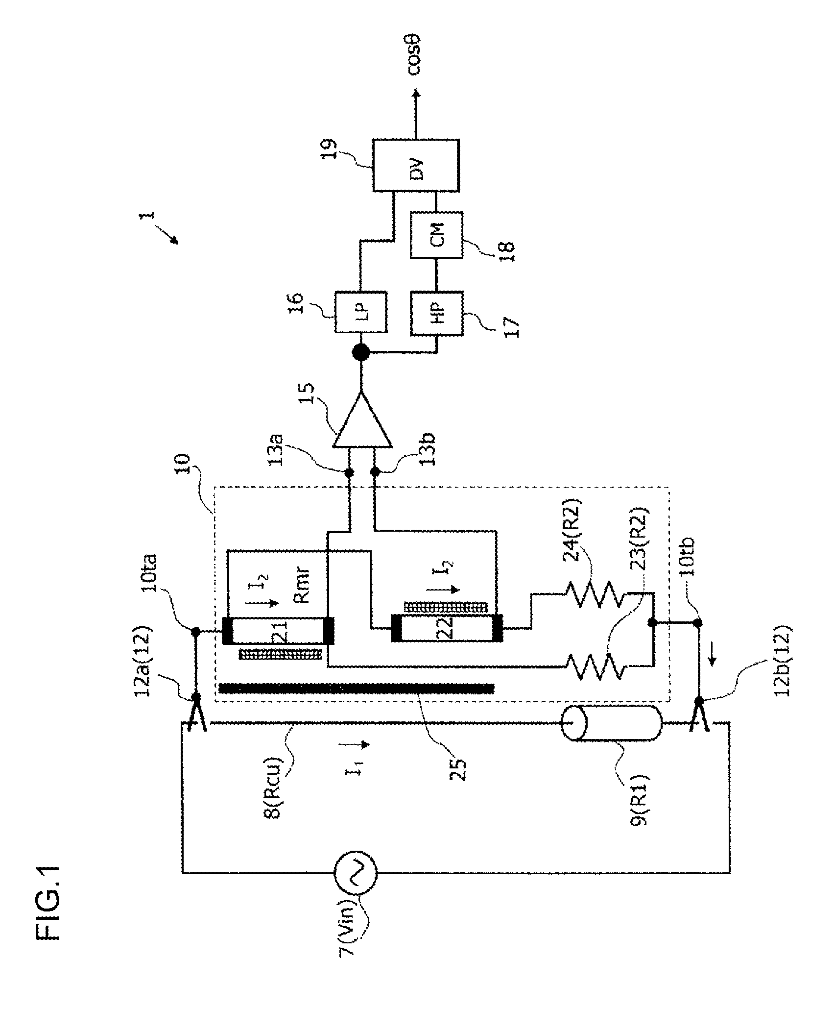
[0031]FIG. 1 illustrates a structure of a power factor measurement apparatus according to the present invention. The power factor measurement apparatus 1 according to the present invention includes coupling ends 12, a power factor sensor 10, a voltage detector 15, a low-pass filter 16, a high-pass filter 17, a rectifier 18, and a divider 19. The power factor measurement apparatus 1 according to the present invention measures a power factor of power consumed at a load 9 (its resistance value is R1) connected to a power supply 7. Herein, the power supply 7 is AC-powered. The power supply 7 is connected with the load 9 via a connection line 8 (its resistance value is Rcu).

[0032]The coupling ends 12 are terminals for connecting the power factor sensor 10 in the power factor measurement apparatus 1 to the power supply 7 in the circuit to be measured in parallel with the load 9. Therefore, the coupling ends 12 are paired, and are discriminated as the coupling ends 12a and 12b.

[0033]FIG. ...

second embodiment

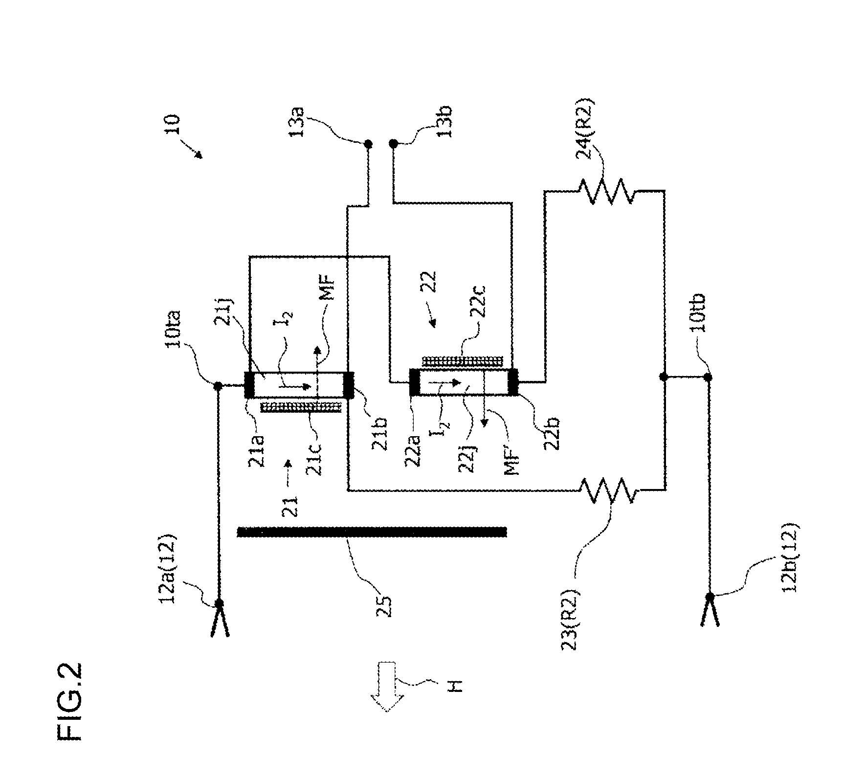
[0066]FIG. 5 illustrates a variation of the magnetic element. As described above, the power factor measurement apparatus 1 according to the present invention can obtain a voltage proportional to a power factor by finding and dividing a DC voltage (proportional to active power) and an AC voltage (proportional to apparent power) based on a differential output in a pair of magnetic elements having the different change rates of electric resistances relative to the same external magnetic field H.

[0067]The magnetic film of the magnetic element has an even function relative to a magnetic field applied from the outside as illustrated in FIG. 3(b) and FIG. 4(b), and a resistance value thereof proportional to the applied magnetic field cannot be obtained by itself. Thus, in the magnetic elements 21 and 22, the magnetic field generating sources such as permanent magnet are arranged as the bias means 21c and 22c near the magnetic films 21j and 22j, respectively, thereby generating a biased magn...

third embodiment

[0080]FIG. 9 illustrates a structure of a power factor measurement apparatus 3 according to the present embodiment. The same parts as the first and second embodiments are denoted as the same reference numerals, and the description thereof will be omitted. The power factor measurement apparatus 3 according to the present embodiment is characterized by magnetic elements 41 and 42. In the magnetic elements 41 and 42, magnetization facilitating axes 41EA and 42EA are tilted and induced toward the longitudinal directions, respectively. Further, the magnetization facilitating axes of the magnetic elements 41 and 42 are induced in the different directions relative to the current I2 flowing on the magnetic films, respectively.

[0081]With such structure, the magnetizations M of the magnetic elements 41 and 42 rotate as M1 and M2 due to the magnetic field H generated by the current I1 flowing in the circuit to be measured, respectively. The orientations of the current I2 flowing in the magneti...


PUM


Abstract

A small-sized power factor measurement apparatus capable of measuring a power factor by one element is desired. The power factor measurement apparatus includes a pair of coupling ends (12) for coupling to a power supply in parallel with a load, two magnetic elements (21, 22) whose changes in electric resistance are different from each other due to the same external magnetic field, a pair of measurement terminals (13) for outputting a differential voltage between the two magnetic elements, a power factor sensor (10) including a pair of sensor terminals (10t) connected to the pair of coupling ends (12), a voltage detector (15) for measuring a voltage between the measurement terminals (13), a low-pass filter (16) connected to the output of the voltage detector (15), a high-pass filter (17) connected to the output of the voltage detector (15), a rectifier (18) connected to the high-pass filter (17), and a divider (19) for dividing the output of the low-pass filter (16) and the output of the rectifier (18).

Description

TECHNICAL FIELD[0001]The present invention relates to an apparatus for measuring a power factor of consumed power in an electric circuit having an inductive load, and particularly to a power factor measurement apparatus using magnetoresistive effects of a magnetic film.BACKGROUND ART[0002]When a load having a reactance component is driven by use of an AC power supply, a phase difference is generated between voltage and current. Consumed power causes active power and reactive power due to the phase difference. An increase in reactive power does not lead to effective use of the power supply, and thus it is desirable that reactive power is reduced and active power is increased.[0003]A rate of active power relative to power supplied from a power supply is called power factor, and is typically expressed as cos θ. Herein, θ is a phase difference between current and voltage. In order to increase active power as much as possible, a power factor in a power consumption circuit needs to be mea...

Claims


Application Information

Patent Timeline
Patent Type & Authority Applications(United States)
IPC IPC(8): G01R21/00G01R21/08
CPCG01R21/06G01R33/0029G01R21/08G01R21/006G01R33/096
Inventor TSUJIMOTO, HIROAKI
Owner OSAKA CITY UNIVERSITY
Why Eureka
Try Eureka