Magnetic field detecting device

a detection device and magnetic field technology, applied in the direction of measurement devices, magnetic measurements, instruments, etc., to achieve the effect of reducing production costs and high accuracy

Active Publication Date: 2015-08-06
AICHI STEEL
View PDF4 Cites 7 Cited by
  • Summary
  • Abstract
  • Description
  • Claims
  • Application Information

AI Technical Summary

Benefits of technology

[0023]Thereby the magnetic field detecting device on the fourth aspect of the present invention makes it possible to obtain an effect by which the signal components selected on the frequency are restrained and the only signal components not selected on the frequency are amplified and are output.
[0024]Accordingly the unnecessary signal components selected on the frequency become small, the magnetic field detecting device on the fourth aspect of the present invention makes it possible to achieve magnetic detection having higher accuracy. The magnetic field detecting device on the fourth aspect of the present invention makes production cost smaller as the magnetic field detecting device on the first through the third aspects of the present invention.

Problems solved by technology

Although two coils are needed in order to apply a bias magnetic field or in order to perform a feedback operation as described above by using a conventional magnetic impedance sensor of a detecting-coil output type, there has been a problem to develop electronic circuit technology that realizes a detecting-coil output type magnetic impedance sensor that is capable of applying a bias magnetic field or capable of improving accuracy through a feedback operation only by using a single coil in order to reduce production cost by reducing the number of components and the number of production process steps of the magnetic impedance element and by reducing the number of defective products while facilitating production.

Method used


Image

  • Magnetic field detecting device
  • Magnetic field detecting device
  • Magnetic field detecting device

Examples


embodiments

First Embodiment

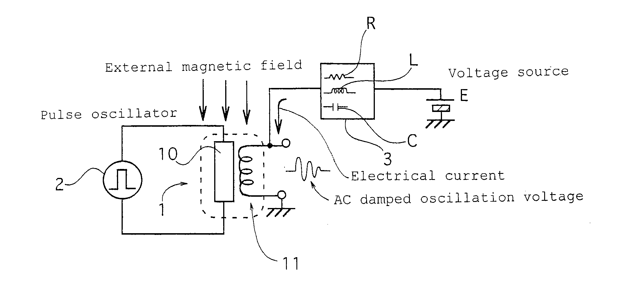
[0040]As shown in FIG. 1, a magnetic field detecting device of a first preferred embodiment comprises a magnetic impedance sensor including a magnetic impedance element 1 in which a pulse electrical current or a high frequency electrical current is applied from an oscillator 2 to an amorphous wire 10 and an alternate current or AC damped oscillation voltage, which is induced in a detecting coil 11 wound around the amorphous wire 10 and that has a magnitude corresponding to an external magnetic field, is output, and an arbitrary magnetic field is applied to the amorphous wire by means of the magnetic field generated on the detecting coil 11 energized by connecting the detecting coil 11 to a voltage source or to a current source E through an impedance network 3 that serves as a decoupling circuit comprising of a resistor R or a coil L or a condenser C or comprising a combination of the resistor R, the coil L, and the condenser C.

[0041]The magnetic field detecting devic...

second embodiment

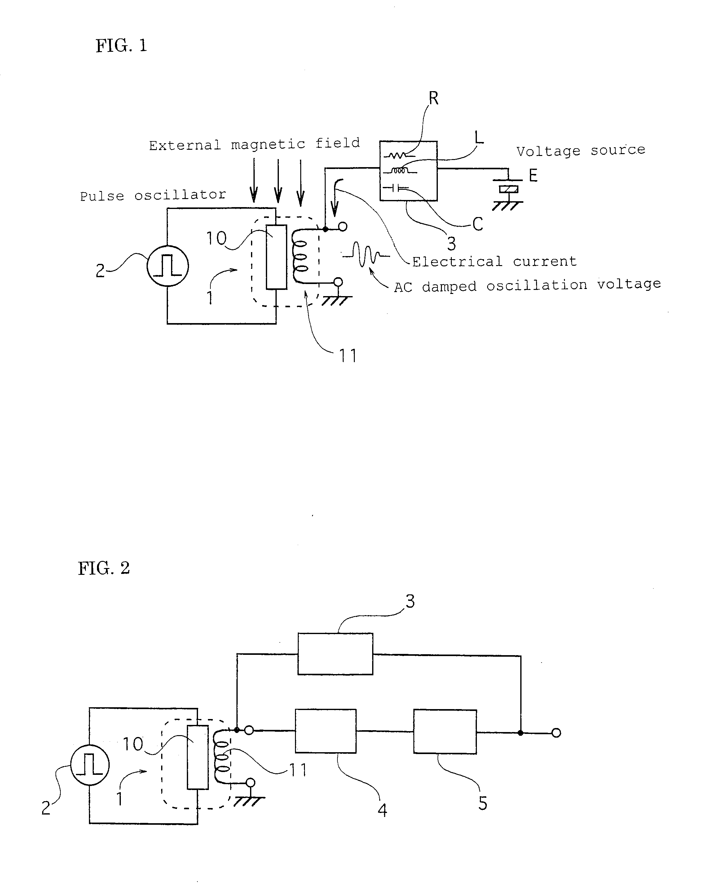
[0046]The magnetic field detecting device of the second preferred embodiment is constructed that an alternate current damped oscillation voltage output by the detecting coil 11 is converted into a magnetic signal in response to the magnitude of an external magnetic field by means of a detection circuit 4, and outputs a magnetic signal having a voltage of a predetermined magnitude amplified by an amplifier 5 as shown in FIG. 2 in the first preferred embodiment, and the detecting coil 11 is energized by connecting to an output terminal of the amplifier 5 serving as a voltage source through the impedance network 3, and a feedback magnetic field is applied to the amorphous wire 10 by means of the magnetic field induced on the detecting coil 11.

[0047]The magnetic field detecting device of the second preferred embodiment, the voltage signal in response to the detected magnetic field is amplified by means of the amplifier 5, and the amplified output is magnetically fed back to the amorphou...

third embodiment

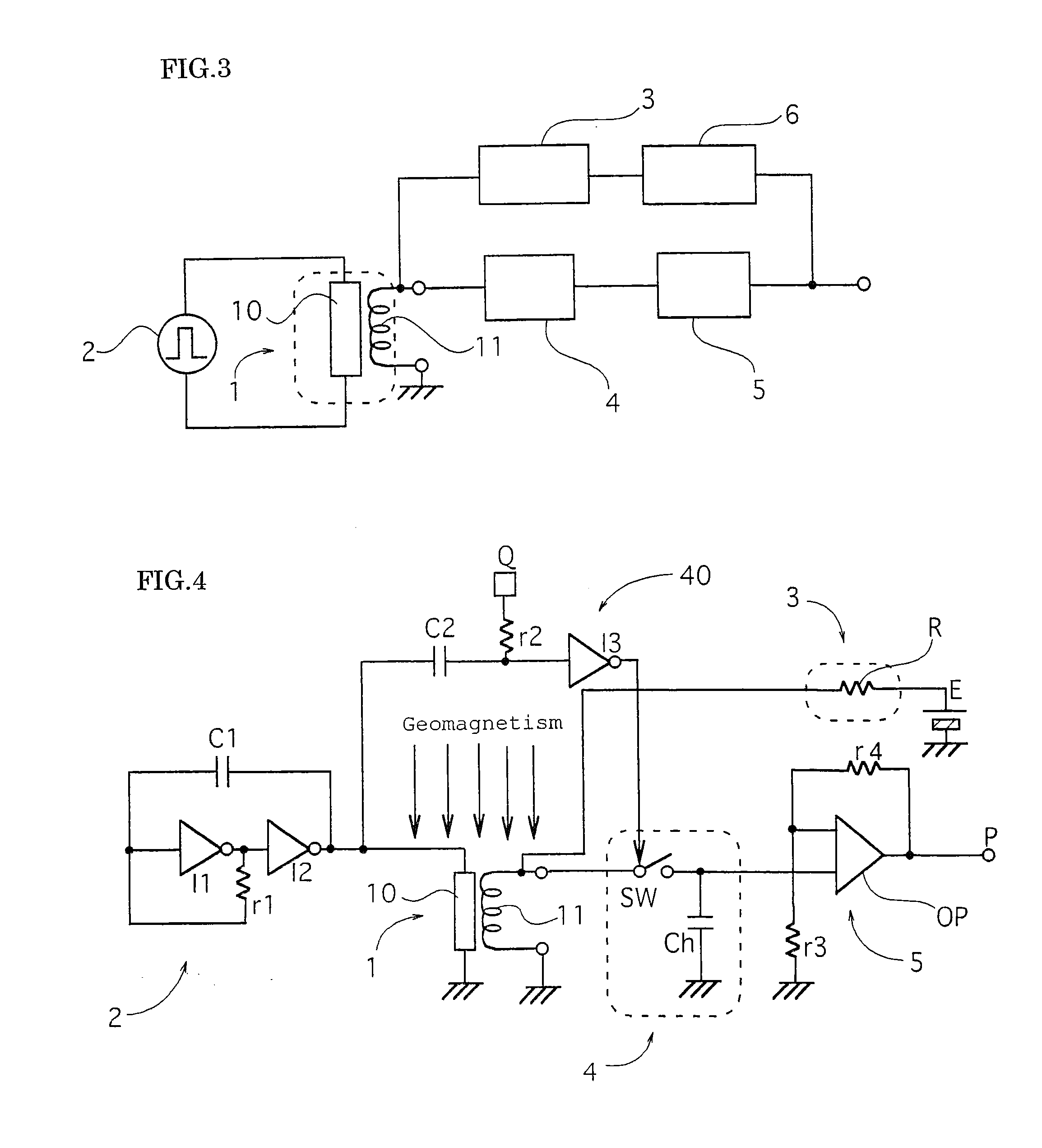
[0051]In the magnetic field detecting device of the third preferred embodiment, the impedance network 3 is connected to the output terminal of the amplifier 5 through a frequency selective circuit 6 as shown in FIG. 3 in the second preferred embodiment, and, as a result, a feedback magnetic field selected in the frequency is applied to the amorphous wire 10.

[0052]In the magnetic detecting device of the third preferred embodiment, only a specific frequency signal component is selected from among output signals of the amplifier 5 and is allowed to pass through, and, as a result, magnetic feedback to the amorphous wire 10 is performed.

[0053]In the third preferred embodiment, the impedance network 3 is connected to the output terminal of the amplifier 5 through the frequency selective circuit 6. As a result, only a frequency signal component selected by the frequency selective circuit 6 among magnetic signals, i.e., among voltage signals output by the amplifier 5 flows into the detectin...


PUM


Abstract

A magnetic field detecting device which comprises a magnetic impedance sensor including a magnetic impedance element 1 in which a pulse electrical current or a high frequency electrical current is applied from an oscillator 2 to an amorphous wire 10 and an alternate current or AC damped oscillation voltage, which is induced in a detecting coil 11 wound around the amorphous wire 10 and has a magnitude corresponding to an external magnetic field, is output, and an arbitrary magnetic field is applied to the amorphous wire by means of the magnetic field generated on the detecting coil 11 energized by connecting the detecting coil 11 to a voltage source or to a current source E through an impedance network 3 comprising of a resistor R or a coil L or a condenser C or comprising a combination of the resistor R, the coil L, and the condenser C.

Description

TECHNICAL FIELD OF THE INVENTION[0001]The present invention relates to a magnetic field detecting device suitable to measure strengths of a direct current and an alternate current magnetic field or to measure a magnetic variation and suitable to detect micro-magnets or the like.PRIOR ART[0002]A magnetic impedance sensor is capable of performing highly-sensitive magnetic detection, and hence is used as a sensor for a magnetic detecting device by which geomagnetism and its slight variation are observed, by which precise magnetic measurement is performed, and by which minute pieces of iron are inspected in physical / chemical / industrial fields {see Patent Literature 1 (Japanese Published Unexamined Patent Application No. 2003-121517), Non-Patent Literature 1 (Transistor Technology, December 2003 Issue, pages 138 to 142), exhibit}.[0003]The magnetic impedance sensor, in which a pulse electrical current or a high frequency electrical current is applied to an amorphous wire of a magnetic im...

Claims


Application Information

Patent Timeline
Patent Type & Authority Applications(United States)
IPC IPC(8): G01R33/09
CPCG01R33/09G01R33/063
Inventor YAMAMOTO, MICHIHARUARAKAWA, HIDEOKAWANO, TAKESHI
Owner AICHI STEEL
Why Eureka
Try Eureka