System and method for interferometrically tracking objects using a low-antenna-count antenna array

a low-antenna-count, interferometric tracking technology, applied in the direction of direction finders using radio waves, instruments, reradiation, etc., can solve the problem of large array, and inability to detect direction, etc. problem, to achieve the effect of large array, large effect on direction determination, and large amount of antennas

Inactive Publication Date: 2015-08-06
THE UNITED STATES OF AMERICA AS REPRESENTED BY THE SECRETARY OF THE NAVY
View PDF4 Cites 16 Cited by
  • Summary
  • Abstract
  • Description
  • Claims
  • Application Information

AI Technical Summary

Problems solved by technology

With short enough baselines, a unique solution for the location at the time of measurement can be found, but the noise inherent in any measurement has a large effect on the direction determination.
However, such a large array requires a considerable amount of antennas, electronics, cabling, as well as the space to install the hardware.
In addition, in practice, even with large numbers of antennas, the direction can still be misidentified.

Method used


Image

  • System and method for interferometrically tracking objects using a low-antenna-count antenna array
  • System and method for interferometrically tracking objects using a low-antenna-count antenna array
  • System and method for interferometrically tracking objects using a low-antenna-count antenna array

Examples


example

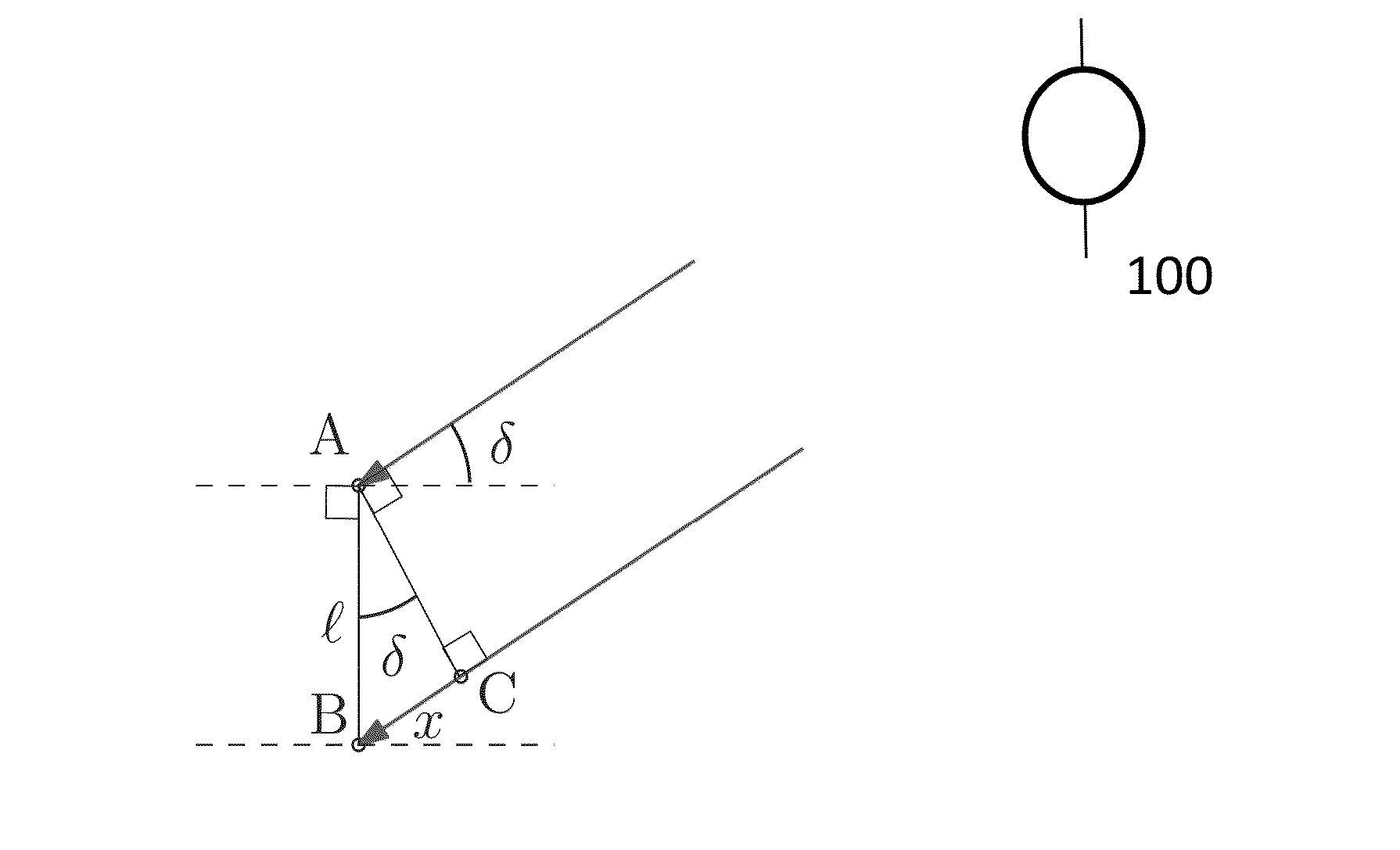
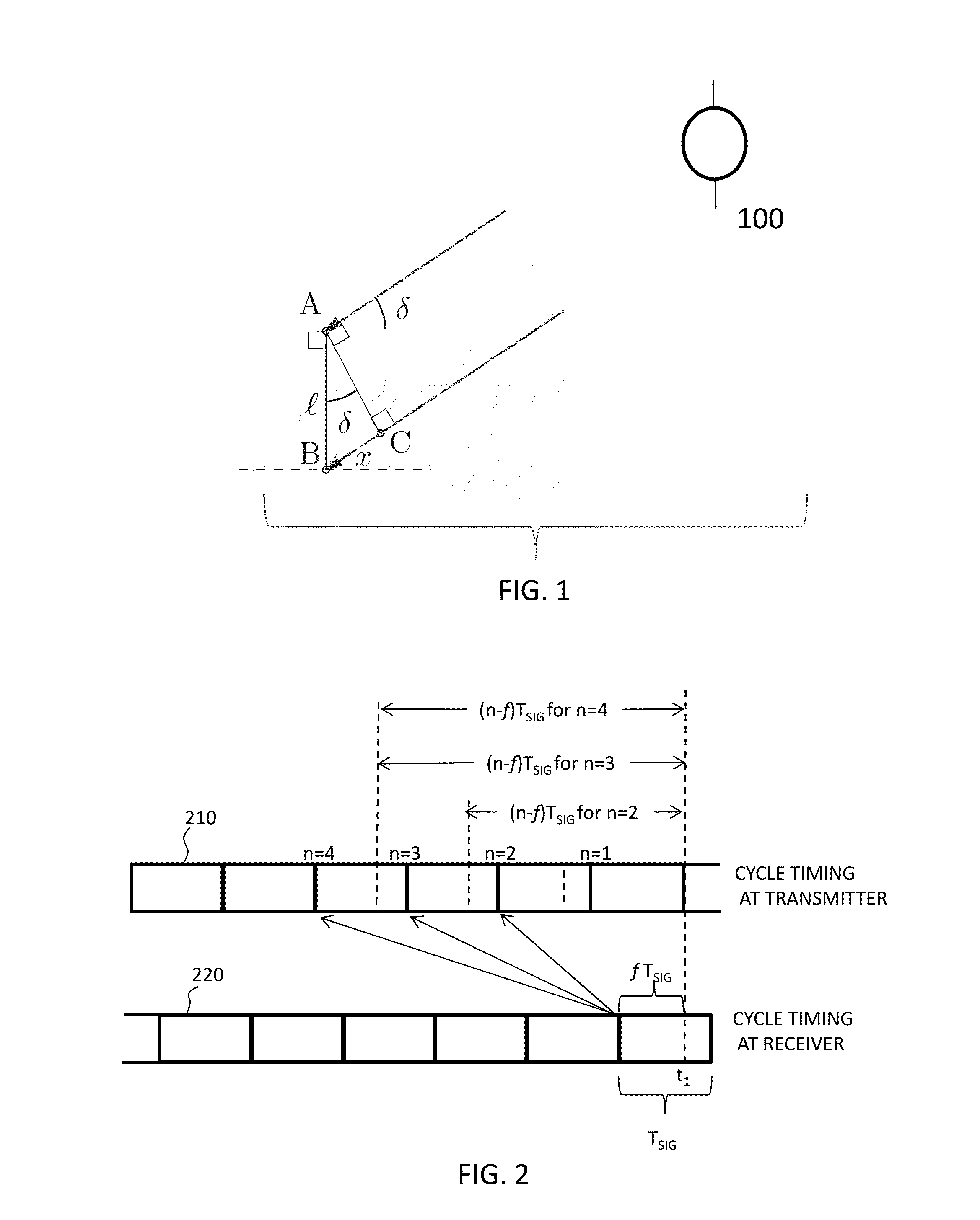
[0077]In one example, the model motion is that of an object moving at constant speed in one dimension in s=sin δ space; linear motion as a function of time,

skpred=spred(tk)=s0+{dot over (s)}(tk−t0).   (9)

where s0 and {dot over (s)} are the intercept and slope from the linear least squares fit. While typically orbital motion is nonlinear over long time periods, for short arcs linear motion may work well, so is sufficient for evaluating simulation results.

[0078]Sample observation data from a two-baseline interferometer was generated at each time step from the direction s computed according to the model motion using the PDF p(f1, f2|sk). This is generated with an acceptance-rejection Monte Carlo method. Modes sequences are determined as discussed above based on this observation data, and a list of mode sequences with estimated parameters produced. This list is ranked by posterior probability weight, with the posterior probability weight providing a gauge of the likelihood of that combi...


PUM


Abstract

A radio-frequency interferometry method for determining parameters of motion of a moving object from phase difference information from an antenna baseline formed of two antennas. At each of a plurality of observation events, compute a posterior probability density function from the phase differences from the baseline, separate the modes with a threshold value of probability density, and compute a probability of each mode. For each possible sequence of modes, determine a mode sequence probability as the product of the probabilities of each mode in that sequence, estimate a χ2 goodness of fit function based on an assumed type of motion. Determine the net probability of each possible sequence of modes as the product of a relative probability derived from the χ2 and the mode sequence probability. Alternately, two or more parallel or colinear baselines are used, and the posterior PDF is a combined PDF over each of the baselines.

Description

CROSS-REFERENCE TO RELATED APPLICATIONS[0001]This Application is a non-provisional under 35 USC 119(e) of, and claims the benefit of, U.S. Provisional Application 61 / 936,068 filed on Feb. 5, 2014, the entire disclosure of which is incorporated herein in its entirety.BACKGROUND[0002]1. Technical Field[0003]This invention is in the field of radio frequency interferometry.[0004]2. Related Technology[0005]Radio frequency interferometry is an established technique for tracking moving objects. In this method, a radio frequency signal is emitted by the object and detected with a interferometer. In an alternative radio frequency interferometry method known as “skin tracking”, a transmitter emits a radio frequency signal, and that signal is reflected off of the metal parts of the object and detected by the interferometer.[0006]These interferometers typically include several antennas. With short enough baselines, a unique solution for the location at the time of measurement can be found, but ...

Claims


Application Information

Patent Timeline
Patent Type & Authority Applications(United States)
IPC IPC(8): G06F17/18G01S13/84
CPCG01S13/84G06F17/18G01S13/003G01S13/42G01S13/878G01S19/43G01S19/44G01S5/0278G01S19/55G01S19/54G01S3/02
Inventor HEALY, LIAM M.
Owner THE UNITED STATES OF AMERICA AS REPRESENTED BY THE SECRETARY OF THE NAVY
Why Eureka
Try Eureka