Load port and efem

a technology of efem and efem, which is applied in the direction of conveyor parts, electric devices, transportation and packaging, etc., can solve the problems of deterioration of yield, corrosion of wiring materials on the wafer surface, corrosion and oxidation, etc., and achieve the effect of improving the quality of the wafer and reducing the supply amount of gas

Active Publication Date: 2015-08-06
SINFONIA TECHNOLOGY CO LTD
View PDF7 Cites 50 Cited by
  • Summary
  • Abstract
  • Description
  • Claims
  • Application Information

AI Technical Summary

Benefits of technology

[0026]According to the embodiment of the invention described above, it is possible to provide a load port and EFEM, which suppress a gas flow to the outside and

Problems solved by technology

In other words, the air atmosphere is likely to permit adhesion of moisture and oxygen to the surface of a wafer, causing corrosion and oxidation.
Further, when a corrosive gas or the like used in the processing apparatus remains on the surface of a wafer, it may cause corrosion of a wiring material on the wafer surface and deterioration of yield.
Further, a corrosion element accelerates a corrosion reaction, and when both moisture and corrosive gas are p

Method used


Image

  • Load port and efem
  • Load port and efem
  • Load port and efem

Examples


first embodiment

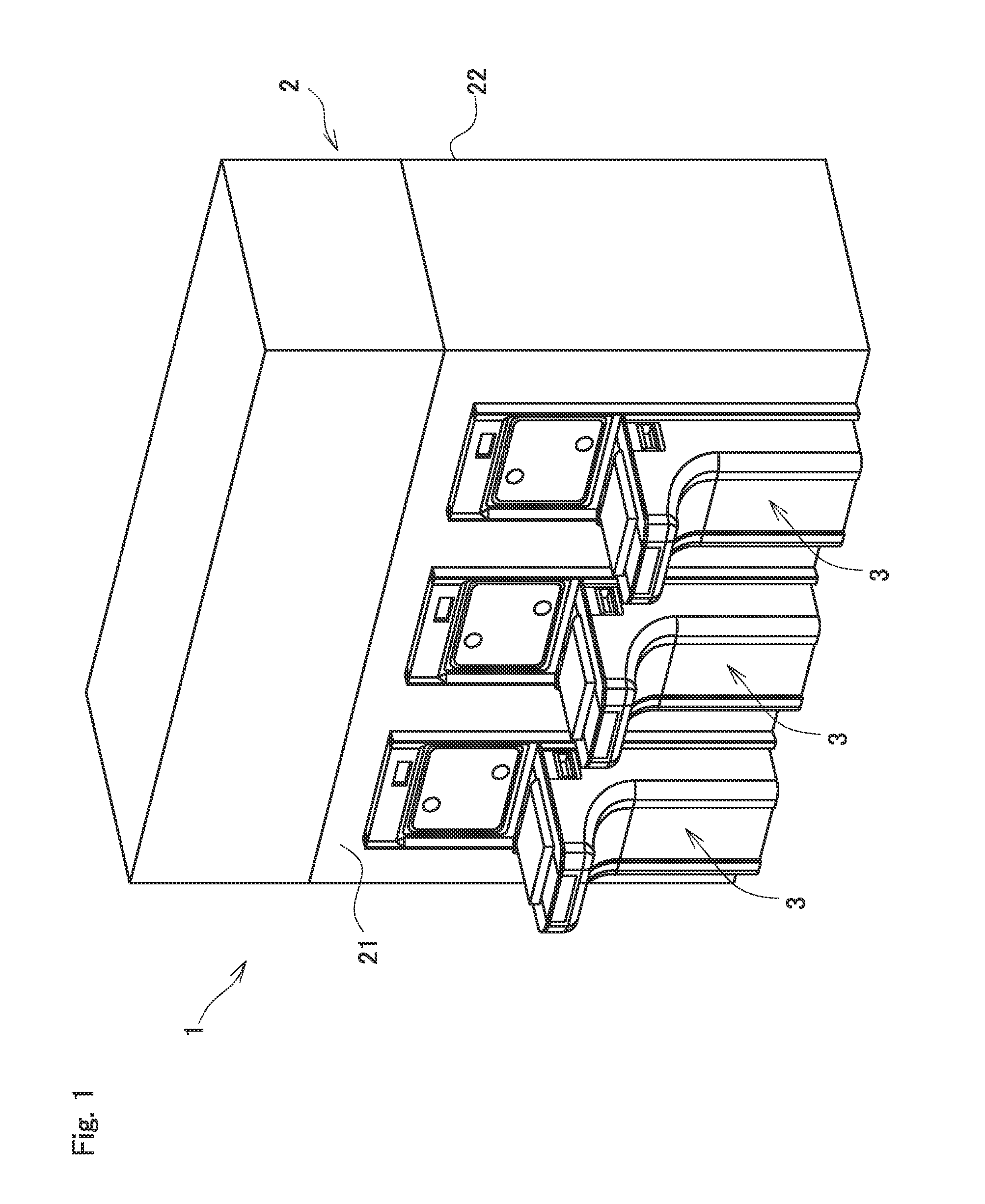
[0048]FIG. 1 shows an EFEM 1 provided with a load port 3 of the first embodiment, and an EFEM having the same. An EFEM 1 includes three load ports connected side by side on a front side 21 constituting a part of a wall of a wafer transport chamber 2 that constitutes a boxed-shaped housing.

[0049]In the present application, when viewed from a wafer transport chamber 2, a direction of the side connected to a load port 3 is defined as a front, a direction of a rear side 22 opposite to the front side 21 is defined as a rear, and a direction perpendicular to a longitudinal and vertical directions is defined as a side. In other words, three load ports 3 are arranged side by side on the side.

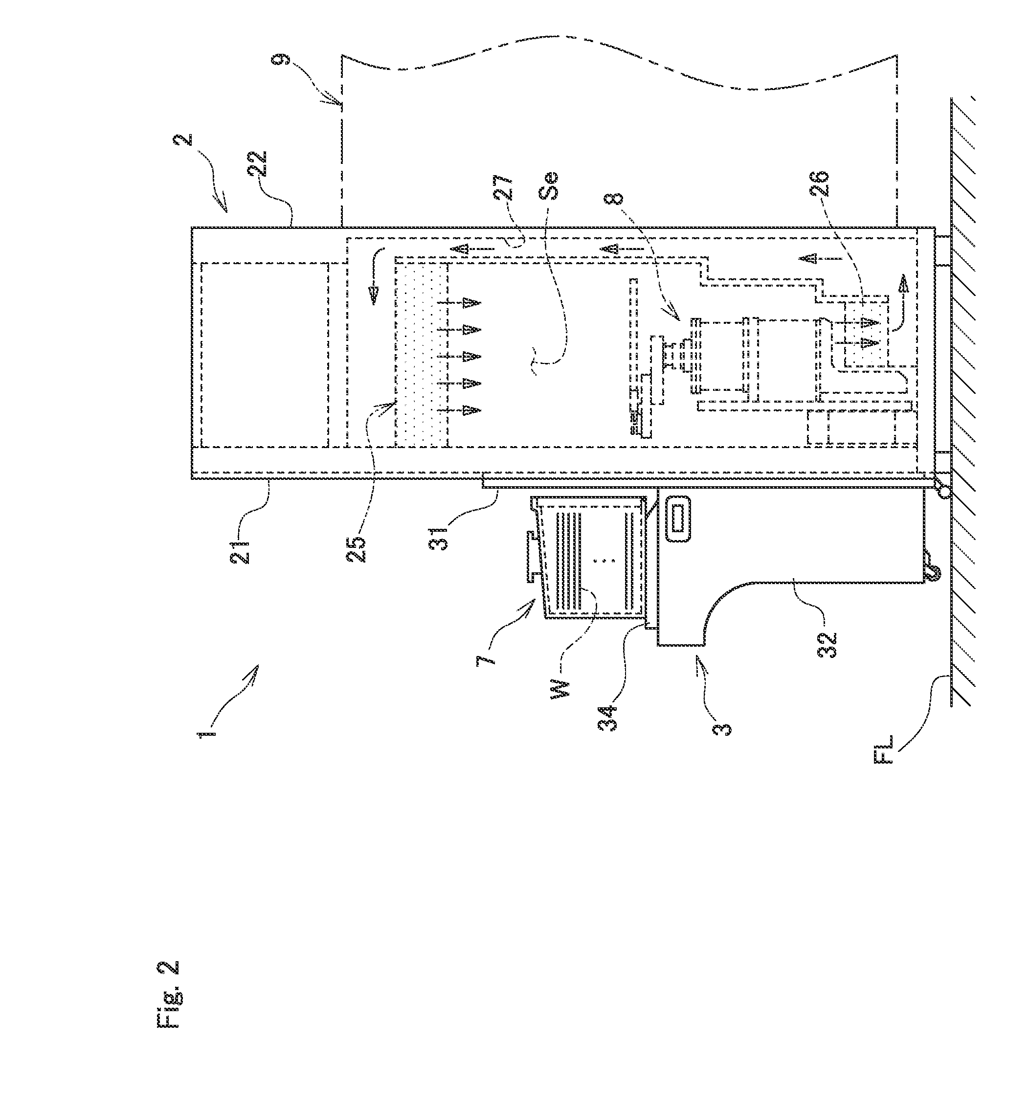
[0050]FIG. 2 is a side view of the EFEM 1 provided with the load port 3. As described above, the load port 3 is connected to the front side 21 of the wafer transport chamber 2. The load port 3 is provided with a panel 31 as a plate-shaped part on the rear side. The panel 31 is integral with the front si...

second embodiment

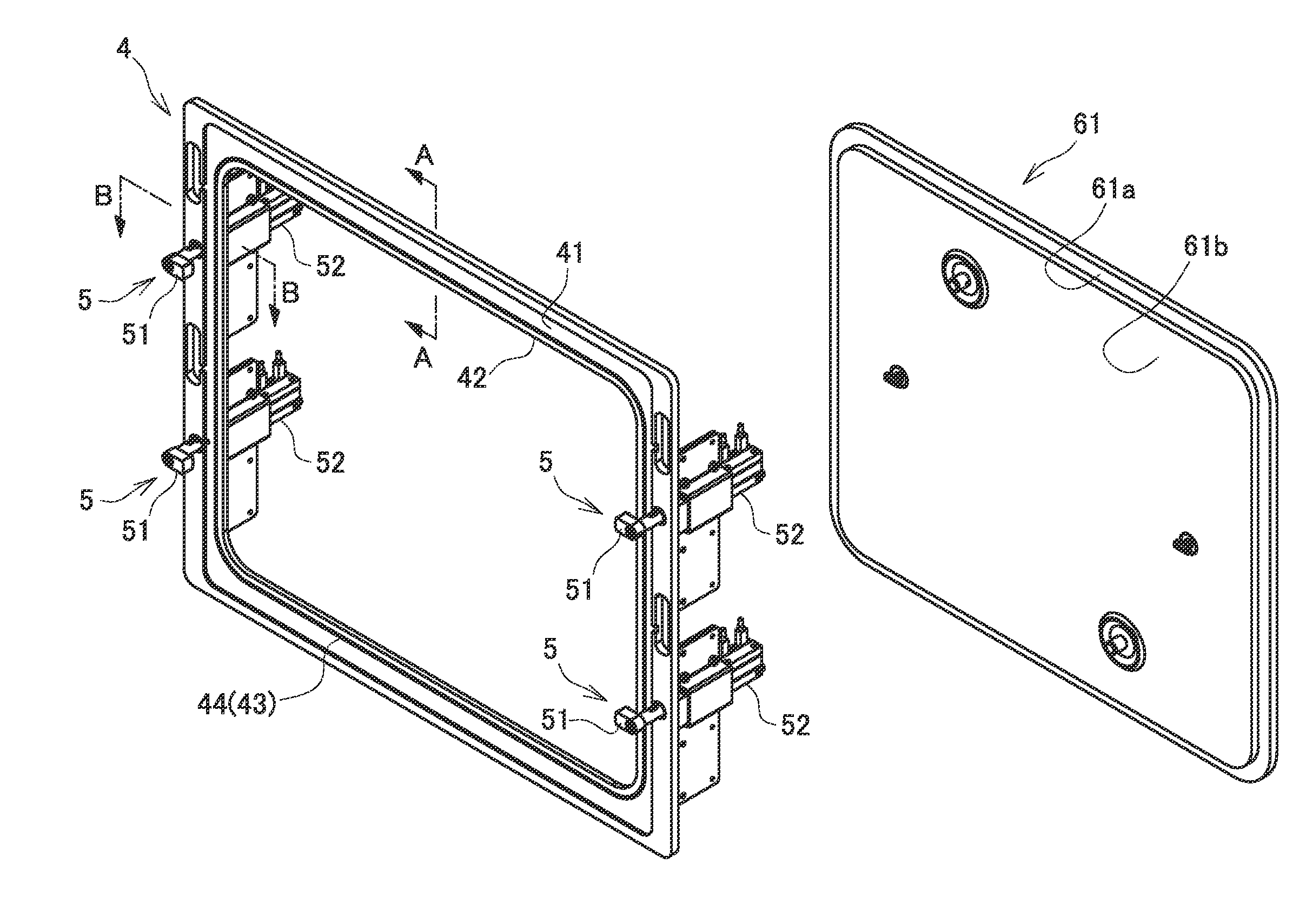
[0093]FIG. 15 shows a window unit 104 constituting a part of an EFEM 101 and load port 103 of a second embodiment. A door part 61 shown in this diagram is similar to the one in the first embodiment. Except for the window unit 104, the configuration is the same as the first embodiment. In this embodiment, the same parts as those in the first embodiment are denoted by the same reference numerals, and a description thereof will be omitted.

[0094]In the window unit 104, a gasket 144 as a plate-shaped elastic member is provided in front of a window frame part 141 and in the vicinity of a peripheral edge of an opening 142. The gasket 144 is formed in a substantially rectangular frame shape, and its inside is the same size as the opening 142. The gasket 144 is fixed to be held between a stop plate 143 and a window frame part 141 formed similarly in a substantially rectangular frame shape.

[0095]As shown in FIG. 16, on the rear side of the window frame part 141, similar to the front side, a g...

third embodiment

[0100]FIG. 17 shows a window unit 204 constituting a part of an EFEM 201 and load port 203 of a third embodiment. A door part 61 shown in this diagram is similar to the one in the first and second embodiments. Except for the window unit 204, the configuration is the same as the first embodiment. In this embodiment, the same parts as those in the first and second embodiments are denoted by the same reference numerals, and a description thereof will be omitted.

[0101]In the window unit 204, a seal member 244 as an elastic member is provided in the vicinity of a peripheral edge of an opening 242 of a window frame part 241. In particular, a seal member 244 as an elastic member is provided so as to extrude slightly inside of a peripheral edge of the opening 242.

[0102]The seal member 244 is formed in a substantially rectangular frame shape as shown in FIG. 18(a). As in the cross section shown in FIG. 18(b), a flat plate portion 244a is formed on the outer periphery, and two elastic portion...


PUM


Abstract

A load port provided adjacent to a wafer transport chamber for taking in and out a wafer W between the wafer transport chamber and a FOUP, includes a plate-shaped part that constitutes a part of a wall of the wafer transport chamber, and has an opening for opening the wafer transport chamber; a door part for opening and closing the opening; a mounting table that is configured to mount a wafer storage container so as to oppose a lid part for opening and closing an internal space to the door part, and to move to and from the plate-shaped part; and an elastic part that is provided on the mounting table side of the plate-shaped part along the peripheral edge of the opening, wherein the elastic part elastically contacts the periphery of the lid part in the wafer storage container by moving the mounting table toward the plate-shaped part.

Description

CROSS-REFERENCE TO RELATED APPLICATIONS[0001]This application claims priority of Japanese Patent Application No. 2014-017819 filed on Jan. 31, 2014. The contents of the applications are incorporated herein by reference in their entirety.BACKGROUND OF THE INVENTION[0002]1. Field of the Invention[0003]Embodiments of the present invention relate to a load port capable of reducing the use amount of gas even when the interior of a wafer transport chamber is set to a special atmosphere, and an EFEM having the same.[0004]2. Description of the Related Art[0005]Conventionally, production of semiconductors has been carried out by various processing steps performed on a wafer. In recent years, circuit miniaturization and high integration of elements have been increasingly promoted. It has been required to maintain a high level of cleanliness around a wafer to prevent adhesion of water and particles to a surface of a wafer. Further, to prevent changes in properties of a surface of a wafer, such...

Claims


Application Information

Patent Timeline
IPC IPC(8): H01L21/677
CPCH01L21/67742H01L21/67775H01L21/67126H01L21/67772
Inventor OCHIAI, MITSUTOSHINAKANO, TAKAAKI
Owner SINFONIA TECHNOLOGY CO LTD
Why Eureka
Try Eureka