Resonant power transmission coils and systems

a technology of power transmission coil and coil, which is applied in the direction of inductance, other medical devices, therapy, etc., can solve the problems of limiting the implantation option, affecting the quality of life of the transcutaneous power cable, and reducing the implantation efficiency of the device, so as to reduce the risk of infection and product life, and improve the quality of li

Active Publication Date: 2015-08-06
TC1 LLC
View PDF5 Cites 38 Cited by
  • Summary
  • Abstract
  • Description
  • Claims
  • Application Information

AI Technical Summary

Benefits of technology

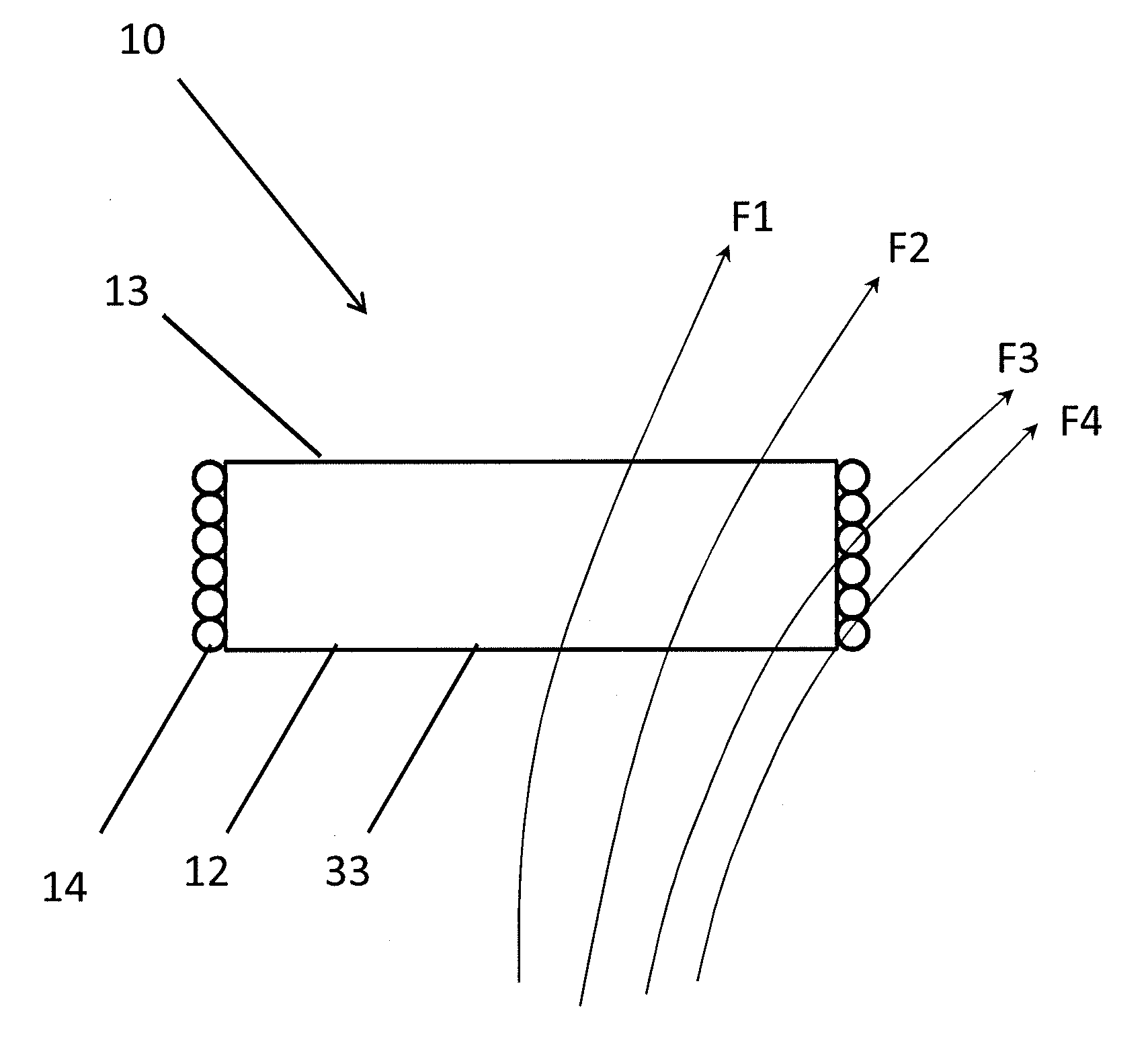
[0024]In some embodiments, the covering is configured to redirect incoming magnetic flux from the external transmitter towards the receiver coil to improve power transfer efficiency.
[0025]A method of improving efficiency in a wireless power transfer system is also provided, comprising the steps of generating magnetic flux with an external transmitter positioned near a patient towards a receiver implanted in the patient, and directing the magnetic flux towards a receiver coil of the receiver with a ferrite covering that surrounds at least a portion of the receiver.

Problems solved by technology

Likewise, a transcutaneous power cable significantly affects quality of life (QoL), infection risk, and product life, among many drawbacks.
Because the components are implanted in the body, a larger receiving coil makes surgical placement more difficult and limits the implantation options.
Thus, this system can be complex to implement, especially in sensitive applications like implantable medical devices.
A larger transmission coil decreases quality of life (QoL) because the patient must carry a larger, heavier coil.
Moreover, larger coils inherently lead to greater complexity.
The system inherently carries the risk of providing too much power to the internal load and / or battery.
Higher power transfer can also lead to excessive heating, which risk damaging the internal organs and tissue.
The system is highly sensitive to receiver coil position and orientation and may not provide adequate power transfer in all cases.
Another drawback with conventional wireless power transmission systems is high susceptibility to interference.
Even minor changes to the field from external factors can significantly affect the transmitter and receiver.
For example, if a metallic object is introduced into the system, it will affect the magnetic flux and in turn the system will not operate efficiently.

Method used


Image

  • Resonant power transmission coils and systems
  • Resonant power transmission coils and systems
  • Resonant power transmission coils and systems

Examples


Embodiment Construction

[0039]In the description that follows, like components have been given the same reference numerals, regardless of whether they are shown in different embodiments. To illustrate an embodiment(s) of the present disclosure in a clear and concise manner, the drawings may not necessarily be to scale and certain features may be shown in somewhat schematic form. Features that are described and / or illustrated with respect to one embodiment may be used in the same way or in a similar way in one or more other embodiments and / or in combination with or instead of the features of the other embodiments.

[0040]Various aspects of the invention are similar to those described in International Patent Pub. No. WO2012045050; U.S. Pat. Nos. 8,140,168; 7,865,245; 7,774,069; 7,711,433; 7,650,187; 7,571,007; 7,741,734; 7,825,543; 6,591,139; 6,553,263; and 5,350,413; and U.S. Pub. Nos. 2010 / 0308939; 2008 / 027293; and 2010 / 0102639, the entire contents of which patents and applications are incorporated herein fo...


PUM


Abstract

An improved wireless transmission system for transferring power over a distance. The system includes a transmitter generating a magnetic field and a receiver for inducing a voltage in response to the magnetic field. In various respects, the receiver is configured to be implanted in a body. The receiver may include a housing enclosing a receiving coil and associated electronic components, a covering around at least a portion of the housing, and at least two wires wrapped around the housing to form a plurality of turns. The covering may be formed of a ferrite material configured to both magnetically shield a respective portion of the internal volume of the housing and redirect incoming magnetic flux from the transmitter to improve efficiency. Methods of use are also provided.

Description

CROSS-REFERENCE TO RELATED APPLICATIONS[0001]This application claims the benefit of U.S. Provisional Patent Application No. 61 / 676,718, filed on Jul. 27, 2012, titled “Resonant Power Transmission Coils and Systems”.INCORPORATION BY REFERENCE[0002]All publications and patent applications mentioned in this specification are herein incorporated by reference to the same extent as if each individual publication or patent application was specifically and individually indicated to be incorporated by reference.FIELD[0003]This disclosure relates generally to methods and apparatus for transmitting and receiving power wirelessly, and in various respects, mechanical circulatory support.BACKGROUND[0004]Powered devices need to have a mechanism to supply power to the operative parts. Typically systems use a physical power cable to transfer energy over a distance. There has been a continuing need for systems that can transmit power efficiently over a distance without physical structures bridging th...

Claims


Application Information

Patent Timeline
Patent Type & Authority Applications(United States)
IPC IPC(8): H02J5/00A61M1/12A61M60/122A61M60/873
CPCH02J17/00A61M1/127H02J5/005A61N1/3787A61M2205/8243H02J50/12A61M60/148H02J50/005H02J50/90H02J50/70A61M60/122A61M60/873H02J2310/23H02J50/10H01F38/14
Inventor HANSEN, JOHN FREDDY
Owner TC1 LLC
Why Eureka
Try Eureka