Method for Assembling a Cartridge for a Smoking Article

a technology for smoking articles and cartridges, which is applied in the direction of conveyors, instruments, roads, etc., can solve the problems of difficult manufacturing fragile, and relatively small components of electronic smoking articles, and achieve the effect of facilitating the insertion of the reservoir substra

Active Publication Date: 2015-08-13
RAI STRATEGIC HLDG INC
View PDF0 Cites 161 Cited by
  • Summary
  • Abstract
  • Description
  • Claims
  • Application Information

AI Technical Summary

Benefits of technology

[0010]The present disclosure relates to assembly of aerosol delivery devices configured to produce aerosol. In one aspect a method for assembling a cartridge for an aerosol delivery device is provided. The method may include providing a reservoir substrate extending at least partially about an atomizer, providing an outer body configured to at least partially receive the reservoir substrate

Problems solved by technology

However, embodiments of electronic smoking articles may be difficult to manufacture.
In this regard, for

Method used


Image

  • Method for Assembling a Cartridge for a Smoking Article
  • Method for Assembling a Cartridge for a Smoking Article
  • Method for Assembling a Cartridge for a Smoking Article

Examples


second embodiment

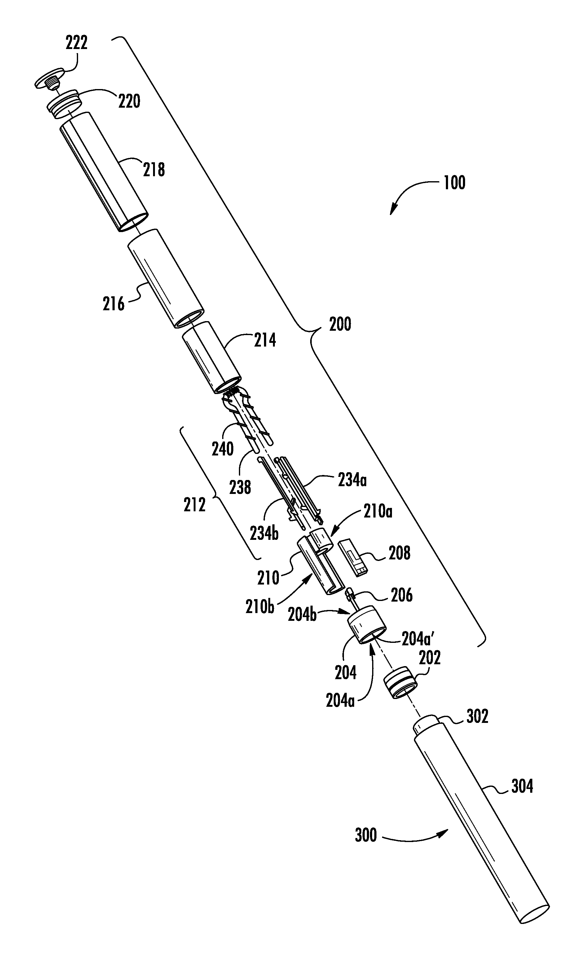
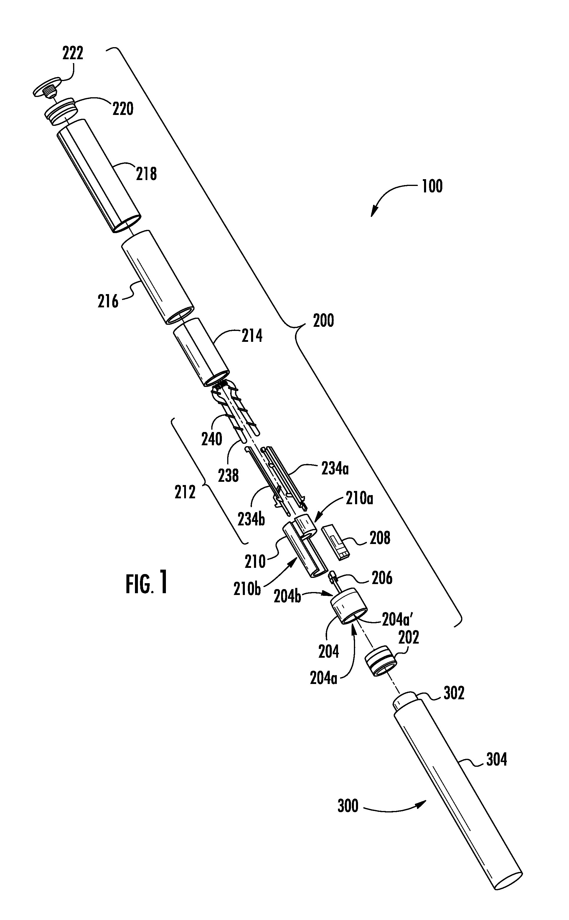
[0296]In the cartridge assembly subsystem 402′, the cartridge is generally assembled with the base 204 oriented in an opposing manner such that components coupled thereto extend downwardly therefrom. In this regard, as illustrated in FIG. 76, the fixtures 1704 of one or more of the transfer members 1700A-C may be employed to facilitate inspection of the terminals 206, 234a, 234b. For example, the fixtures 1704 may hold the base 204 such that the attachment end 204a thereof extends upwardly. Accordingly, an end view camera 2702 positioned above the base 204 may inspect the radial position of the terminals 206, 234a, 234b.

[0297]Further, as illustrated in FIG. 77, the fixtures 1704 may include one or more apertures 2704a, 2704b extending therethrough. Accordingly, as illustrated in FIG. 76, a side view camera 2706 may be positioned to look through one or more of the apertures 2704a, 2704b to determine a distance to which the terminals 206, 234a, 234b extend from the inner end 204b of ...

first embodiment

[0298]The inspection subsystem 418 may additionally include one or more cameras configured to inspect the partially assembled cartridge following crimping of the outer body 216 to the base 204. For example, as illustrated in FIG. 78, when inspecting the cartridge assembly subsystem 402, the inspection subsystem 418 may include an end view camera 2802 configured to capture images inside of the outer body 216. In this regard, the end view camera 2802 may be positioned above the rail 616 downstream of the crimper 1118, such that when a carriage 600 is directed under the end view camera, the end view camera may capture one or more images of the inside of the outer body 216. Thereby, a controller may determine whether or not the reservoir substrate 214 is present, which is a desired condition, or missing, which is an undesired condition.

[0299]Further, the cartridge assembly subsystem 402 may include a side view camera 2804 configured to capture images of a side of the partially assembled...


PUM

PropertyMeasurementUnit
Fractionaaaaaaaaaa
Flow rateaaaaaaaaaa
Electrical resistanceaaaaaaaaaa

Abstract

The present disclosure relates to systems, apparatuses, and methods for assembling cartridges for aerosol delivery devices. The cartridges may be assembled by transporting carriages between various substations at which parts are added to a base. In another assembly method, the base may be moved between a plurality of robots which direct the base downwardly into contact with components to couple the components therewith. An inspection system may inspect the cartridges at various stages of completion.

Description

CROSS-REFERENCE TO RELATED APPLICATIONS[0001]This application claims the benefit of U.S. Provisional Application No. 61 / 939,446, filed Feb. 13, 2014, which is entirely incorporated herein by reference in its entirety.FIELD OF THE DISCLOSURE[0002]The present disclosure relates to a cartridge for aerosol delivery devices such as smoking articles, and more particularly to methods for assembling a cartridge for smoking articles including an atomizer. The atomizer may be configured to heat an aerosol precursor, which may be made or derived from tobacco or otherwise incorporate tobacco, to form an inhalable substance for human consumption.BACKGROUND[0003]Cigarettes, cigars and pipes are popular smoking articles that employ tobacco in various forms. For example, a traditional type of cigarette has a substantially cylindrical rod-shaped structure and includes a charge, roll or column of smokable material, such as shredded tobacco (e.g., in cut filler form), surrounded by a paper wrapper, th...

Claims


Application Information

Patent Timeline
IPC IPC(8): A24F47/00G01R31/02B61B13/04A24F40/10A24F40/70A24F40/80
CPCA24F47/008G01R31/025B61B13/04A24F40/10A24F40/80A24F40/70A61M15/06A61M2207/10B23P19/04A61M2205/3334A61M2205/43A61M2205/8206A61M11/042Y10T29/49913A24F40/46B23P11/005A24C5/34B65G2201/0267H01C3/16H01C17/04H05B2203/037H01C3/08A24F40/50B23P21/004B25J15/0047B25J11/005A61M2207/00
Inventor AMPOLINI, FREDERIC PHILIPPENESTOR, TIMOTHY BRIANFLINCHUM, JR., JACK GRAYBROWN, WAYNE DOUGLASWATSON, NICHOLAS HARRISONNOVAK, III, CHARLES JACOBBRINKLEY, PAUL A.COVINO, JAMES ROBERTDEPIANO, JOHNDICKINSON, EDWARD LOUISHARRIS, EUGENE R.KEOUGH, KEVIN EDWARDSMITH, DAVID JAYHOOK, JOHNLACOURSE, MICHAELMETCALF, ROBERTHART, STEVENPELLETIER, DAVIDBOURQUE, MARCCAMBRAY, NATHANIELWOLBER, JOHN WILLIAMMCCLELLAN, JAMES WILLIAMMONGILLO, STEVEN R.SILVEIRA, FRANK S.LAINE, MICHAELGUENTHER, JR., QUENTIN PAUL
Owner RAI STRATEGIC HLDG INC
Why Eureka
Try Eureka