

Cryogenic engine system
- Summary
- Abstract
- Description
- Claims
- Application Information
AI Technical Summary
Benefits of technology
Problems solved by technology
Method used
Image

Examples
Example
DETAILED DESCRIPTION OF THE DRAWINGS
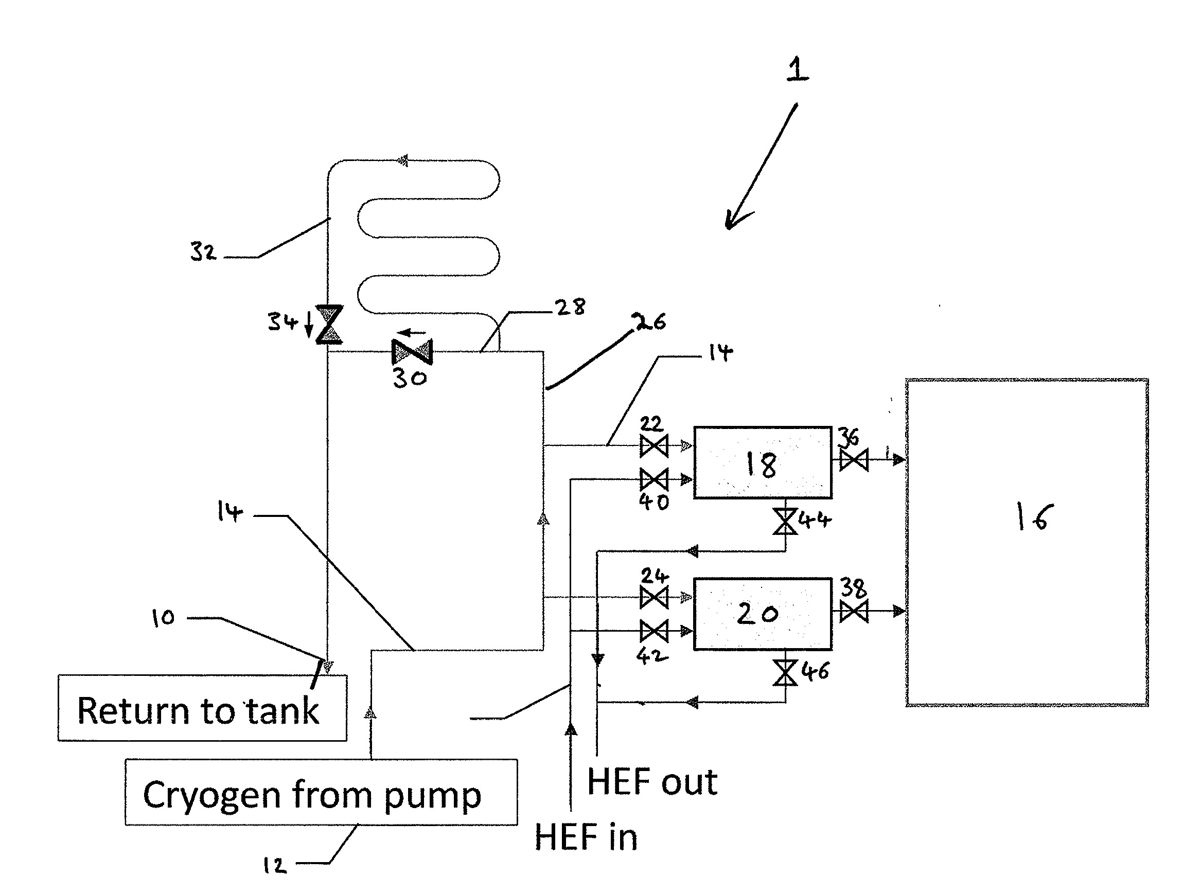
[0114]FIG. 1 shows a cryogenic engine system 1 according to an embodiment of the present invention.
[0115]Liquid cryogen is stored in a suitable storage vessel, such as a tank 10, at high pressure. A typical storage pressure is approximately 3 bar. The cryogen is fed from the tank 10 to a cryogenic pump 12 where it is pressurised and then admitted to a first conduit 14. Typically, the cryogen is pressurised by the pump 12 to a pressure of 150 bar and then admitted to the first conduit 14 at a rate of 25 grams / s.
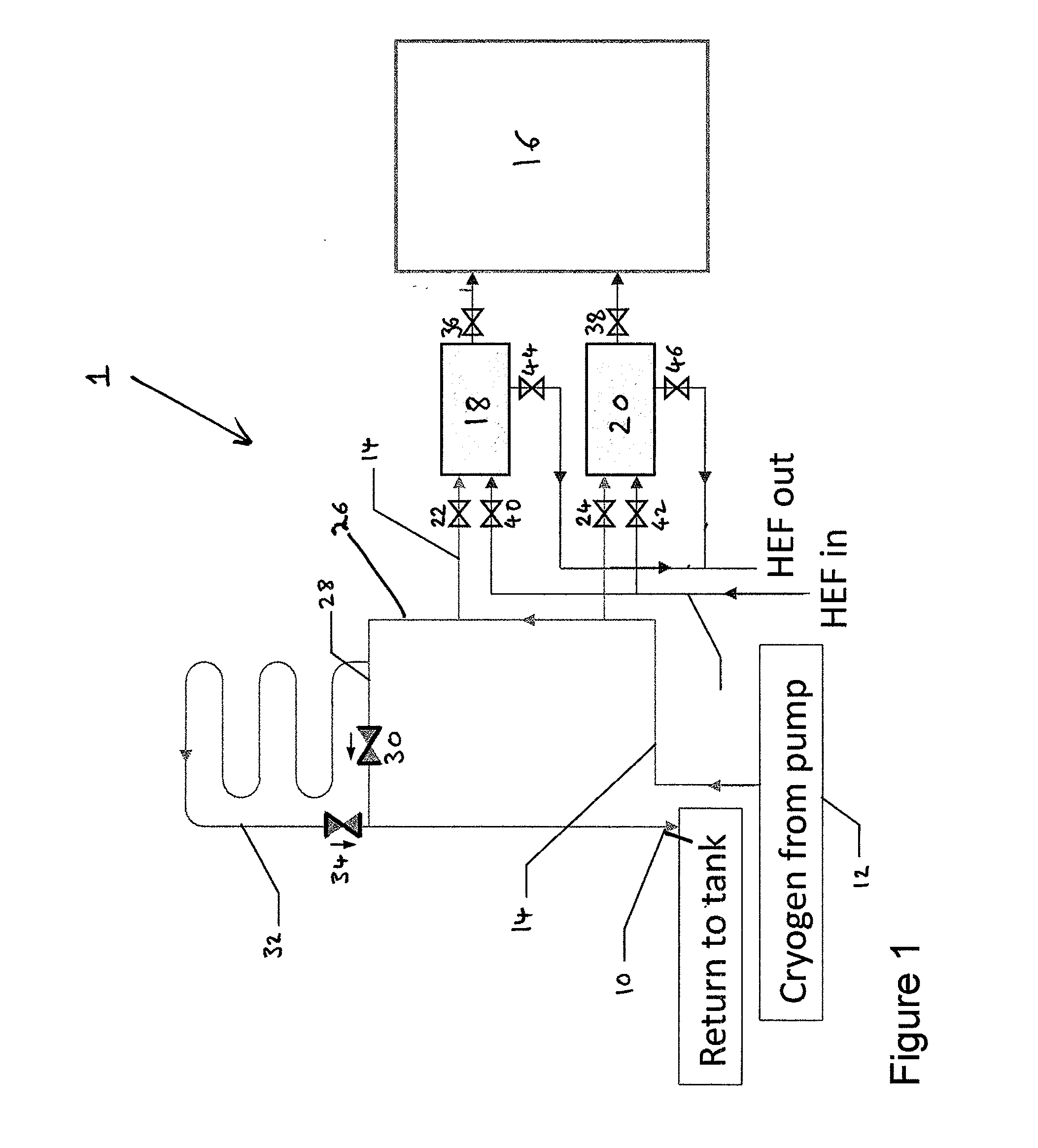
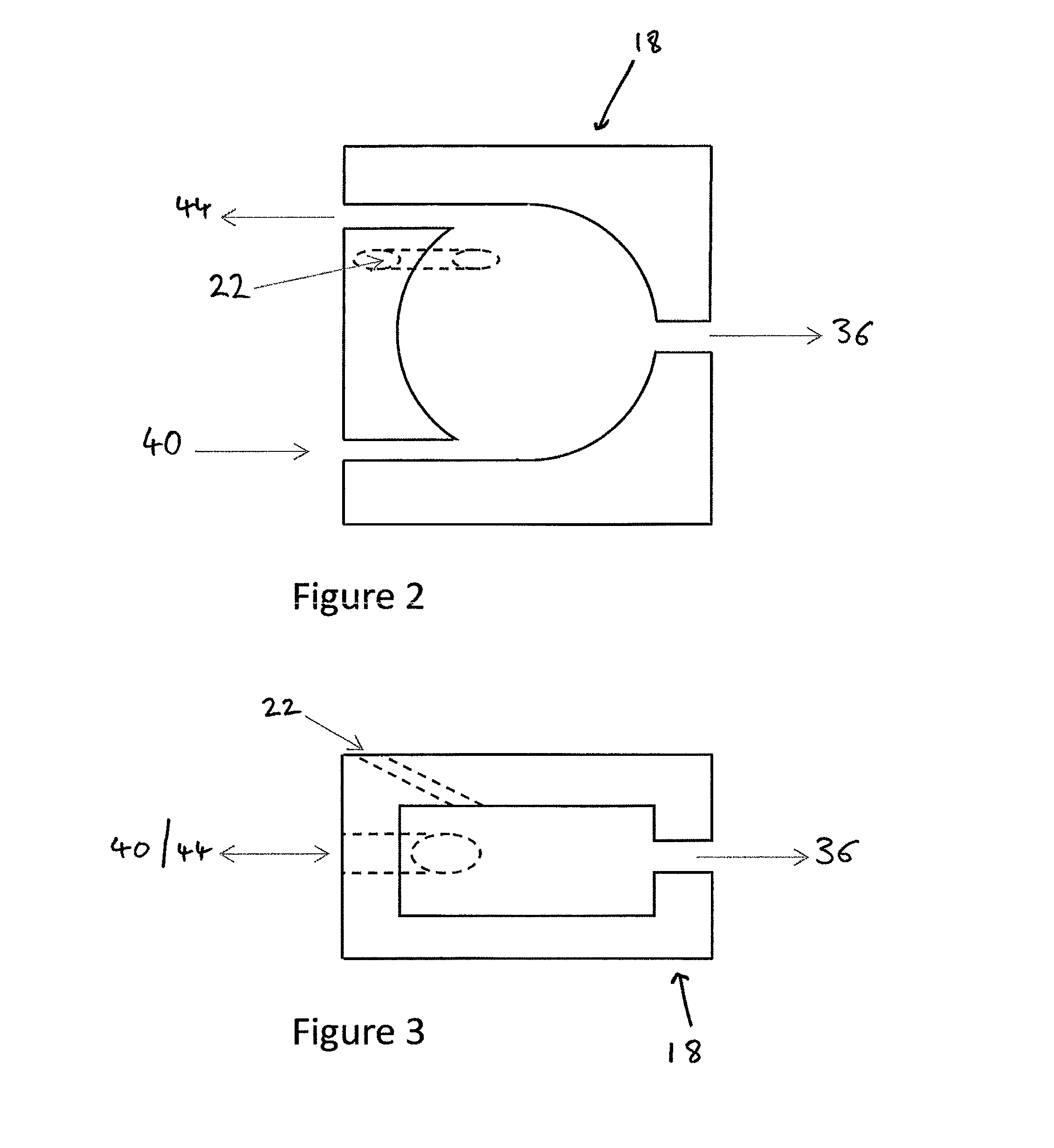
[0116]Before being admitted to a cryogenic engine 16, some or all of the cryogen flow from the pump 12 is directed to at least one pre-mixing chamber 18, 20 through the first conduit 14, which comprises a well-insulated pipe. In the exemplary embodiment shown in FIG. 1, the system comprises two pre-mixing chambers 18, 20. However, any number of pre-mixing chambers 18, 20 can equally be used. In the exemplary embodiment shown in FIG. 1, appro...
PUM
 Abstract
Description
Claims
Application Information