Motion control system and method with energy harvesting

a technology of energy harvesting and motion control system, which is applied in the direction of motors, applications, structural/machine measurement, etc., can solve the problems of not always practical to provide electrical power from an external source to a motion control system, cumbersome wiring, and the cost of wiring electrical power to the site of a movable mechanism, etc., to achieve the effect of enhancing safety, preserving energy, and increasing yield

Active Publication Date: 2015-08-13
JAIN IRRIGATION SYSTEMS LIMITED
View PDF11 Cites 30 Cited by
  • Summary
  • Abstract
  • Description
  • Claims
  • Application Information

AI Technical Summary

Benefits of technology

[0022]Another advantage of the present invention is that it harvests and stores energy that may be otherwise wasted in current systems. Another advantage of the invention, as applied to irrigation, is that it also provides for a more controlled distribution pattern that can be tailored for specific conditions. Agricultural fields are not uniform in either their water or nutrient requirements. Sprinklers designed in accordance with an embodiment of the present invention can be configured and instructed to optimize water distribution patterns to accommodate particular sets of conditions, such as soil moisture content, soil type, crop variety, weather conditions, etc., any number of times by wirelessly changing parameters stored in the sprinkler's memory. This allows for precision irrigation of the crop and increased yields.
[0023]Another advantage of the invention is that it can control the motion of mechanical assemblies such as turnstiles to enhance safety or to better control the flow of people or materials. Further, when applied to the dispensing of a quantity of fluid or powder or granulated substance in a controlled fashion in which the flow is powered by the force of gravity, the present invention can not only control the flow of material but can also measure the amount of material dispensed and wirelessly report any problems or error conditions, without requiring any power source other than the power in the gravity flow itself.
[0024]An apparatus designed in accordance with the present invention harvests energy, for example the energy of flowing water (hydraulic), or the energy caused by people or objects pushing against a turnstile or gate, or the energy of a flowing fluid or granular substance which is moving due to gravity. Thus it is an advantage that the control and communication functions which are desired in an apparatus do not require any additional source of power, eliminating the expense of running wires or providing some other source of energy. Also, because power is now resident in the apparatus itself, for example a sprinkler, the apparatus can include, for example, sensors which require power and / or a wireless communication device and / or other auxiliary devices such as an information display or a valve. The wireless communication device is referred to as a ‘wireless communication module’.
[0025]An apparatus designed in accordance with the invention can either be programmed ahead of time or programmed in the field by a portable computer with the appropriate wireless network hardware and software. Each individual apparatus (e.g. sprinkler) has its own antenna that communicates to a remote unit which
[0027]2) allows the system manager to control the operation of each individual apparatus; and
[0028]3) immediately informs the system manager of any problems or errors.

Problems solved by technology

However, it is not always practical to provide electrical power from an external source to a motion control system.
This may be because the movable mechanism is portable and wiring is cumbersome or because no electrical energy is available at the site of the movable mechanism.
Additionally, there are costs associated with wiring electrical power to the site of a movable mechanism.
In the case of a rotating sprinkler, for example, the energy source which actually moves the rotating sprinkler mechanism is generally in the form of pressurized flowing water and electrical power may not be convenient or easy to obtain at the site of a sprinkler.
Another movable mechanism at which electrical energy may not be convenient or easy to obtain is a human-powered turnstile, which is pushed by a person in order to gain access.
This rooster tail effect causes small and uneven distribution patterns.

Method used


Image

  • Motion control system and method with energy harvesting
  • Motion control system and method with energy harvesting
  • Motion control system and method with energy harvesting

Examples


Embodiment Construction

[0047]In the following detailed description, reference is made to the accompanying drawings that form a part hereof, and in which is shown by way of illustration specific embodiments which may be practiced. These embodiments are described in sufficient detail to enable those skilled in the art to practice the invention, and it is to be understood that other embodiments may be utilized and that various changes may be made without departing from the spirit and scope of the present invention. The following detailed description is, therefore, not to be taken in a limiting sense. The term ‘system’ and ‘apparatus’ are used interchangeably in the current specification and they refer to the same structure.

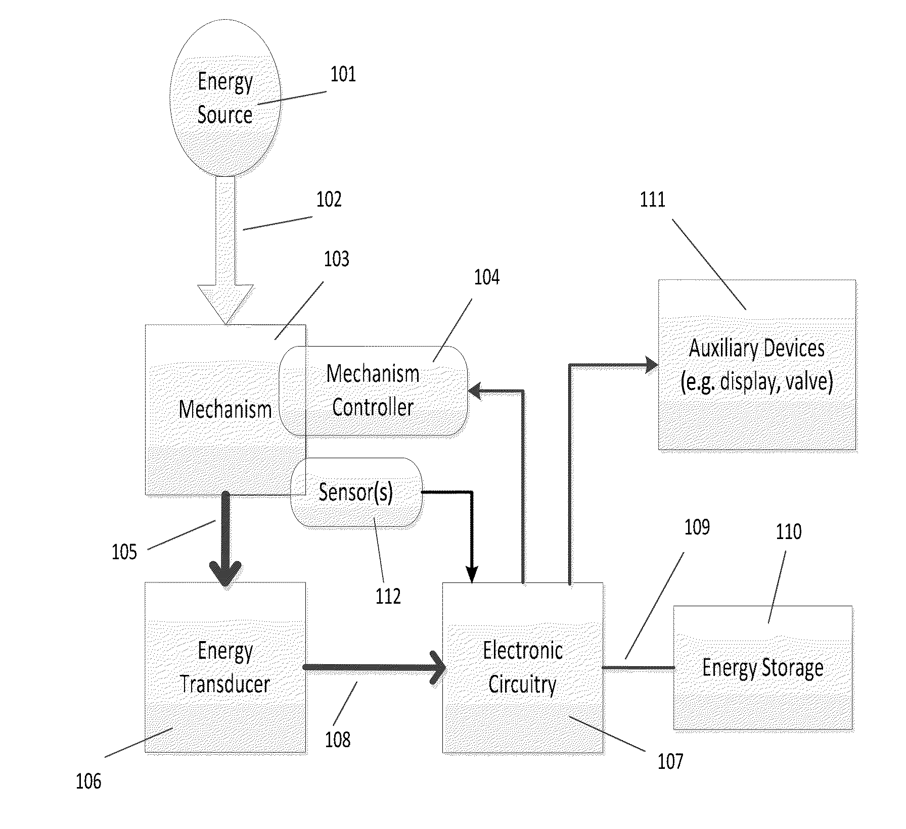
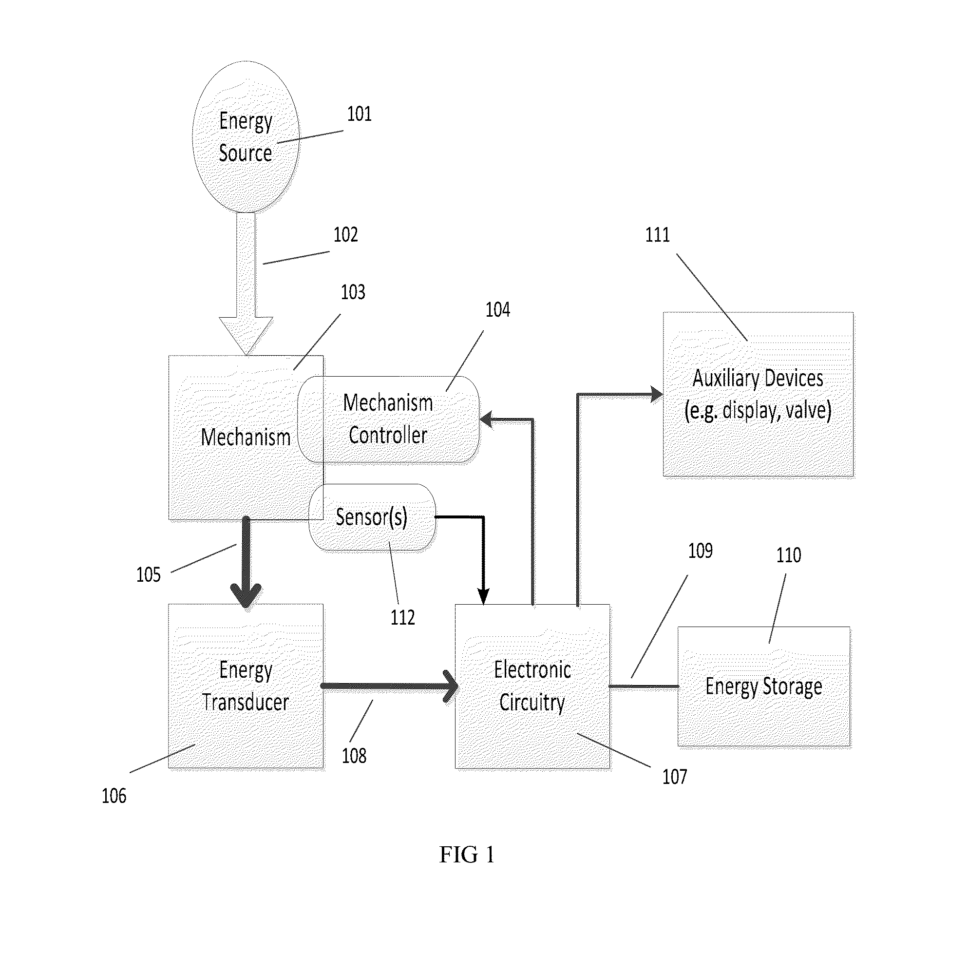
[0048]FIG. 1 is a motion control apparatus with energy harvesting. An energy source 101 provides kinetic energy 102 to move a movable mechanism 103. The energy source is external to the movable mechanism and thereby referred to as an external energy source. The energy source may be hydraul...


PUM


Abstract

A motion control apparatus and method is disclosed. The motion control apparatus comprises a movable mechanism coupled to an external energy source, the energy source providing kinetic energy to the mechanism. An energy conversion module is mechanically coupled to the mechanism for converting kinetic into electrical energy. An electronic circuit is coupled to the energy conversion module and a storage module and a mechanism controller is coupled to the electronic circuit. A sensor module is coupled to both the electronic circuit and the movable mechanism to sense the movement of the movable mechanism to determine speed of the movable mechanism and transmit speed information to the electronic circuit. The method comprises applying energy to a movable mechanism, converting kinetic to electrical energy, storing the electrical energy converted, controlling the motion of the mechanism and sensing the movement of the mechanism.

Description

FIELD OF THE INVENTION[0001]The present invention relates to a system and method for controlling the motion of a mechanism while harvesting electrical energy from kinetic energy of the mechanism's motion. An external energy source, such as the pressurized flowing water, is coupled to the mechanism and provides the kinetic energy from which the electrical energy is harvested. The motion control system comprises, for example, a rotating mechanism, and a means to control an aspect of the mechanism's motion, for example its rotational speed. As energy is harvested from the kinetic energy of the mechanism's motion, the energy source which powers the motion control features of the apparatus is the same energy source which powers the movement of the mechanism. In a preferred embodiment, there is no need to run wires from a remotely-located power source to bring electrical energy to the motion control system. The system may contain a rechargeable battery or some other form of electrical ene...

Claims


Application Information

Patent Timeline
Patent Type & Authority Applications(United States)
IPC IPC(8): F03B17/06A01G25/16G05B15/02
CPCF03B17/06A01G25/16G05B15/02F03G5/06F03G7/08B05B3/0486Y02E10/20F03G5/065F03G3/04
Inventor DEFRANK, MICHAEL PATRICKGOLDBERG, JACKHOUK, RANDY L.HALL, JONATHAN R.
Owner JAIN IRRIGATION SYSTEMS LIMITED
Why Eureka
Try Eureka