Rotating pump

a technology of rotating pump and sealing mechanism, which is applied in the direction of rotary/oscillating piston pump components, machines/engines, liquid fuel engines, etc., can solve the problems of inability to ensure the durability of sealing mechanism, lack of sealing ability of sealing mechanism, and inability of pump to have the required endurance against the discharge of brake fluid, etc., to ensure the stability of sealing gap, reduce the risk of resinous member breakage, and increase the effect of pressur

Inactive Publication Date: 2015-08-13
ADVICS CO LTD
View PDF2 Cites 1 Cited by
  • Summary
  • Abstract
  • Description
  • Claims
  • Application Information

AI Technical Summary

Benefits of technology

[0012]The resinous member is pressed by the high pressure of the fluid, but stopped by the deformation-suppressing member of the seal functioning portion from being deformed into the low-pressure region of the gap, thereby minimizing the risk of breakage of the resinous member to ensure the stability of sealing the gap. This enables the rotating pump to discharge the fluid at an increased pressure.

Problems solved by technology

The above described conventional sealing mechanisms, however, need to have a large clearance between the casing and the outer rotor for meeting a pressure requirement because of design limitations in terms of production tolerance of the pump.
It is, therefore, impossible for the pump to have the required endurance against the discharge of the brake fluid at high pressure.
For instance, the resin member may deform into the clearance between the casing and the outer rotor, thereby resulting in breakage of the resin member, which leads to a lack of sealing ability of the sealing mechanism.
It is, thus, difficult to ensure the durability of the sealing mechanisms and achieve the discharging of the brake fluid at high pressure.

Method used


Image

  • Rotating pump
  • Rotating pump
  • Rotating pump

Examples


first embodiment

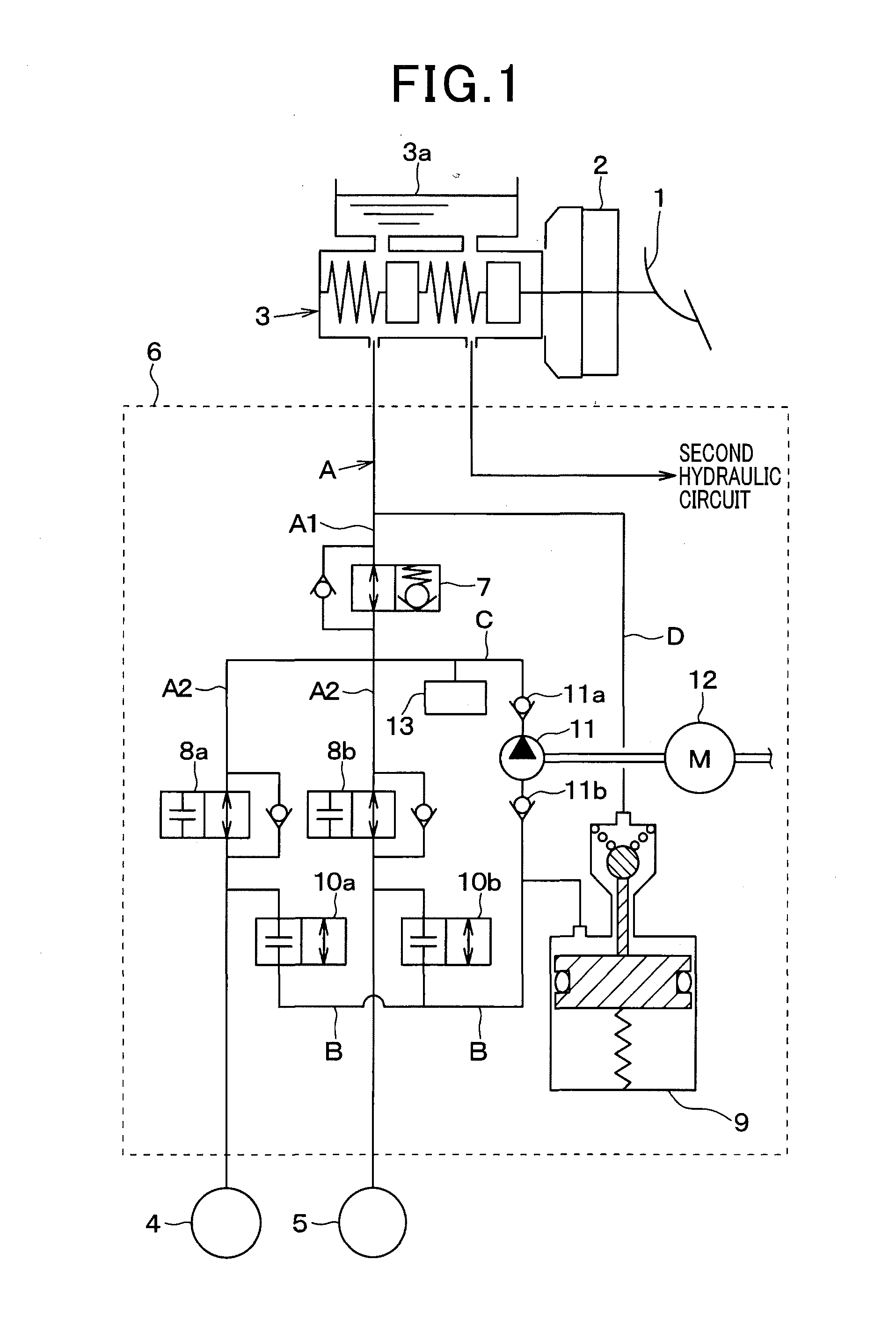
[0032]Referring to FIG. 1, there is shown an automotive brake system equipped with a rotating pump that is a part of a hydraulic circuit of the brake system. The brake system, as referred to herein, is designed as a so-called diagonal split system which includes two brake hydraulic circuits one of which controls the right front and the left rear wheel and the other of which controls the left front and the right rear wheel, but may be engineered as a front / rear split system.

[0033]The brake system is equipped with a brake pedal 1 (i.e., a brake actuating member) to be depressed by a vehicle occupant or driver for applying the brakes to the vehicle, a brake booster 12, a master cylinder 3, wheel cylinders 4 and 5, and a brake pressure control actuator 6. The master cylinder 3, as will be described later in detail, works to produce a braking hydraulic pressure in response to an operation of the brake actuating member (i.e., the brake pedal 1).

[0034]The brake pedal 1 is connected to the ...


PUM


Abstract

A rotating pump includes an outer and an inner rotor disposed in a casing with a gap between the casing and the outer rotor. The rotating pump also includes a first and a second sealing member in the casing to define a low-pressure region and a high-pressure region within the gap. Each of the first and second sealing members is made up of a seal functioning portion and an elastically pressing portion. The seal functioning portion includes a resinous member and a deformation-suppressing member. The resinous member contacts the outer rotor and a low-pressure side inner surface of the casing to establish a difference in pressure between the low-pressure region and the high-pressure region. The deformation-suppressing member works to stop the resinous member from deforming undesirably. This minimizes the risk of breakage of the resinous member and enables the rotating pump to discharge the fluid at an increased pressure.

Description

[0001]The present application claims the benefit of priority of Japanese Patent Application No. 2014-22442 filed on Feb. 7, 2014, the disclosure of which is incorporated herein by reference.BACKGROUND OF THE INVENTION[0002]1.Technical Field of the Invention[0003]This disclosure relates generally to a rotating pump designed to suck and then discharge fluid, and more particularly to such a rotating pump which is useful for a brake system working to suck and discharge brake fluid to regulate the pressure thereof for controlling the braking force.[0004]2. Background Art[0005]Japanese Patent First Publication No. 2002-295376 teaches use of an internal gear pump, such as a trochoid pump, as a rotating pump for an automotive brake system. This type of rotating pump is made up of an inner rotor, an outer rotor, and a casing. The inner rotor is equipped with outer teeth formed on an outer periphery thereof. The outer rotor is equipped with inner teeth formed on an inner periphery thereof. Th...

Claims


Application Information

Patent Timeline
Patent Type & Authority Applications(United States)
IPC IPC(8): F04C2/14F04C15/00F04C15/06
CPCF04C2/14F04C15/0015F04C15/06F01C19/005F04C2/102F04C15/0034
Inventor HISADA, YOSHITAKEFUCHIDA, TAKESHI
Owner ADVICS CO LTD
Why Eureka
Try Eureka