Roadway safety barrier

a safety barrier and road technology, applied in roadway safety arrangements, roads, construction, etc., can solve the problems of excessive misalignment of the constituent parts of the barrier, inadequate structure, excessive misalignment of the barrier, etc., and achieve the effect of increasing the absorption of kinetic energy

Pending Publication Date: 2022-02-24
INGECID INVESTIGACION Y DESARROLLO DE PROYECTOS
View PDF12 Cites 3 Cited by
  • Summary
  • Abstract
  • Description
  • Claims
  • Application Information

AI Technical Summary

Benefits of technology

[0014]The road safety barrier object of this invention, which comprises prefabricated concrete parts including: bottom parts forming the base of the barrier, top parts forming a vertical body or element of the barrier and, o...

Problems solved by technology

The disadvantage of this barrier, likewise with the barriers made up of a single part of concrete, is that they do not have a structure suitable to be deformed and to significantly absorb the kinetic energy of a vehicle in the event of an impact and, therefore, they do not minimise the harmful effects to those involved in the accident.
These attaching elements, like others on the market, have the disadvantage that, in the event of the barrier receiving a very strong impact, the constituent parts of the barrier are excessively misaligned, and the top parts then could be released from the bottom parts of the barrier and said top parts could be broken at the assembly areas of the attaching means.
One problem with existing barriers is that, in the event of an impact, it is the vehicle that absorbs the energy, with the consequent high risk of injury to occupants.
However, the problem with the use of these displaceable barriers is that they cannot be installed in...

Method used


Image

  • Roadway safety barrier
  • Roadway safety barrier
  • Roadway safety barrier

Examples


Embodiment Construction

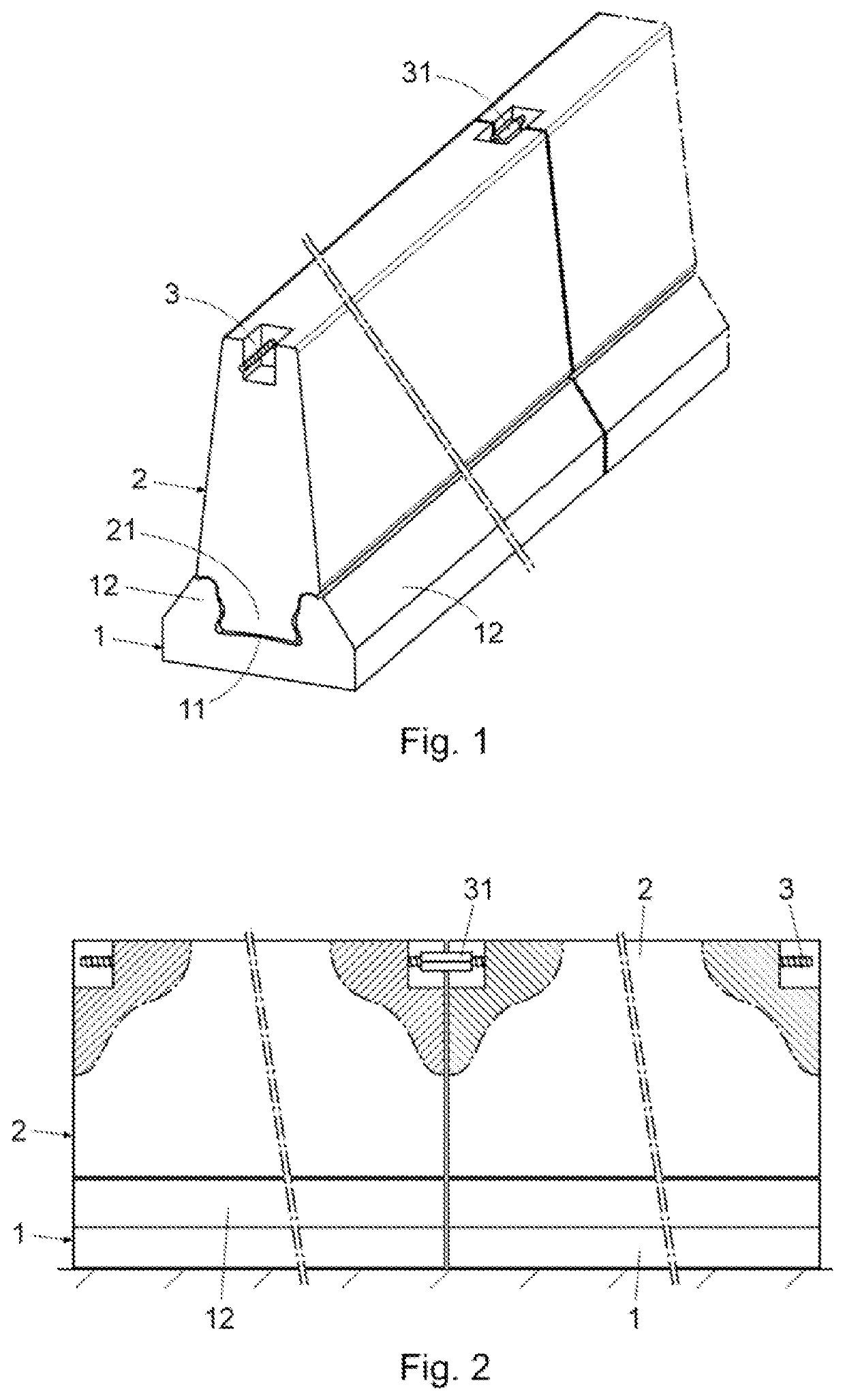
[0035]As can be seen in FIG. 1, the road safety barrier of the invention comprises bottom parts (1) and top parts (2) of concrete, prefabricated and of constant cross-section in the longitudinal direction.

[0036]As can be seen in FIGS. 1 and 2, both the bottom parts (1) and the top parts (2) are facing each other at their longitudinal ends forming respective alignments.

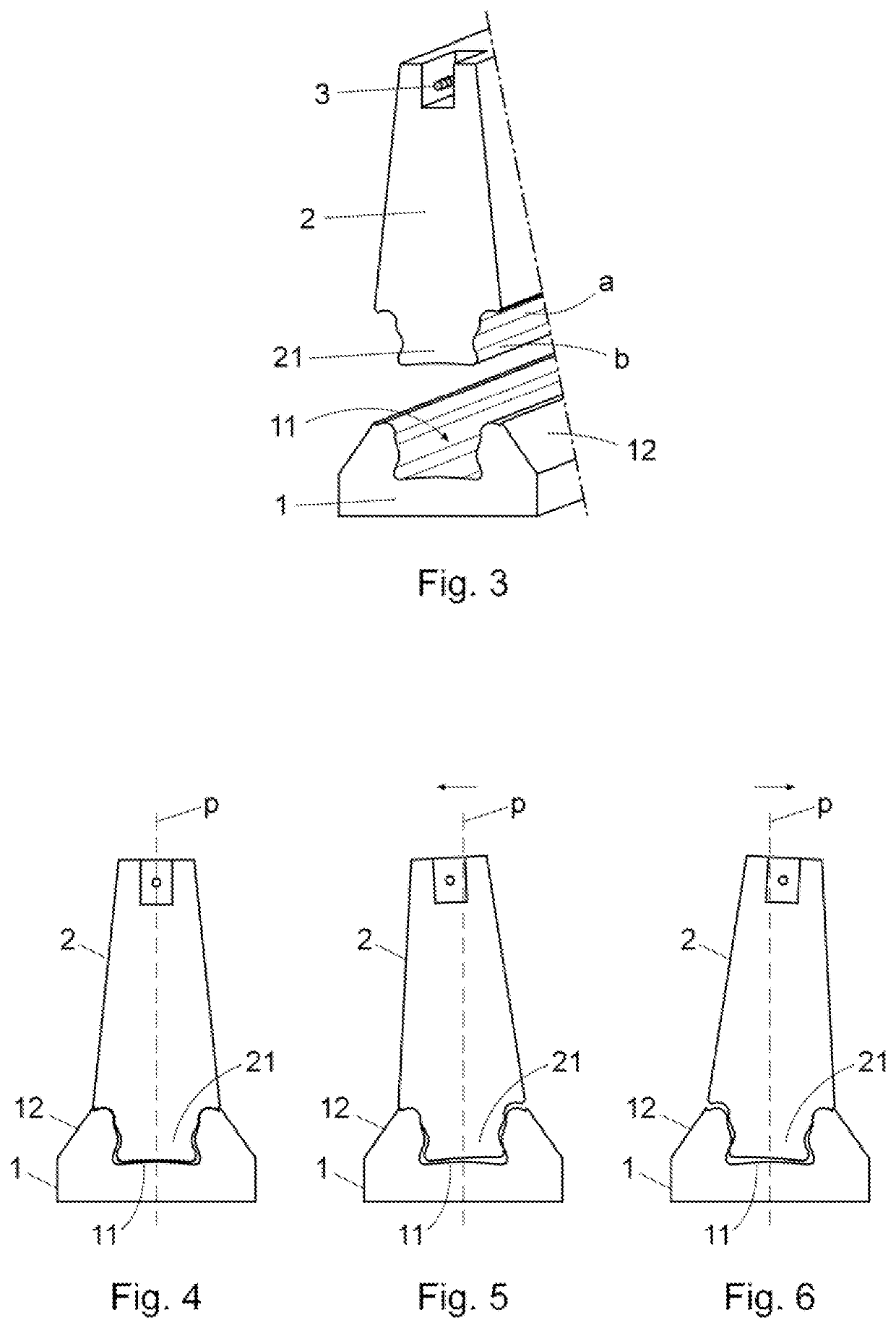
[0037]The successive top parts (2) are connected by attaching means, consisting of threaded rods (3), of the dywidag type, which pass through the interior of said top parts (2) and which are fixed at their ends by threaded sleeves (31). These attaching means cooperate with the coupling of the extension (21) and the channel (11) in limiting the lateral rotation of the top parts (2) in the event of an impact of a vehicle against the barrier.

[0038]Each of the bottom parts (1) has, on its upper surface, a longitudinal channel (11) for coupling in the longitudinal direction, like a slide, a longitudinal extension (21) protr...


PUM


Abstract

Road safety barrier comprising: concrete bottom parts (1); concrete top parts (2) coupled on the bottom parts (1), and attaching means (3, 31) of the successive top parts (2) at their opposite ends. The bottom parts (1) have an upper surface provided with a longitudinal channel (11) for coupling in the longitudinal direction and with the possibility of limited vertical displacement of a longitudinal extension (21) protruding from a lower surface of the top parts (2); the channel (11) and the extension (21) have similar cross-sections and dimensions calculated so that the top part performs a lateral rotation of a determined amplitude, in the event of a vehicle impact, and absorbs a significant part of its kinetic energy.

Description

TECHNICAL FIELD[0001]The present invention relates to a road safety barrier comprising a series of prefabricated concrete parts with constant cross-section, facing each other at their longitudinal ends and which include: bottom parts making up the base of the barrier, and top parts making up the body of the barrier, said top parts being attached by attaching means which connect the facing ends thereof.[0002]This road safety barrier is within the field engaged in the manufacture of protective elements intended to delimit vehicle traffic areas.BACKGROUND ART[0003]Currently, barriers used to delimit vehicle traffic areas constituted of concrete parts with constant cross-section along their length and which are attached to the ground or which simply are supported thereon, are widely known.[0004]Among concrete barriers, barriers are known formed by a series of concrete elements having a single part body, and barriers formed by bottom parts making up a base of the barrier and top parts wh...

Claims


Application Information

Patent Timeline
IPC IPC(8): E01F15/08
CPCE01F15/088E01F15/083E01F15/0476E01F15/08
Inventor RICO ARENAL, JOKINBALLESTER MUÑOZ, FRANCISCOHELGUERA LÓPEZ, DAVIDCEREZO LEZA, MARCOSCAVADA LAZA, FERNANDOTHOMAS GARCÍA, CARLOSPOLANCO MADRAZO, JUAN ANTONIOSETIÉN MARQUÍNEZ, JESÚS
Owner INGECID INVESTIGACION Y DESARROLLO DE PROYECTOS
Why Eureka
Try Eureka