
System and method for determining the position of defects on objects, coordinate measuring unit and computer program for coordinate measuring unit

a technology of object position and position information, applied in the field of system and method for determining the position of defects on objects, coordinate measuring units and computer programs for coordinate measuring units, can solve the problems of inability to provide accurate position information, inability to achieve accurate stage interferometer and environmental control, and inability to achieve accurate results. the effect of high accuracy

Inactive Publication Date: 2015-08-13
KLA TENCOR TECH CORP
View PDF45 Cites 26 Cited by
  • Summary
  • Abstract
  • Description
  • Claims
  • Application Information

AI Technical Summary

Benefits of technology

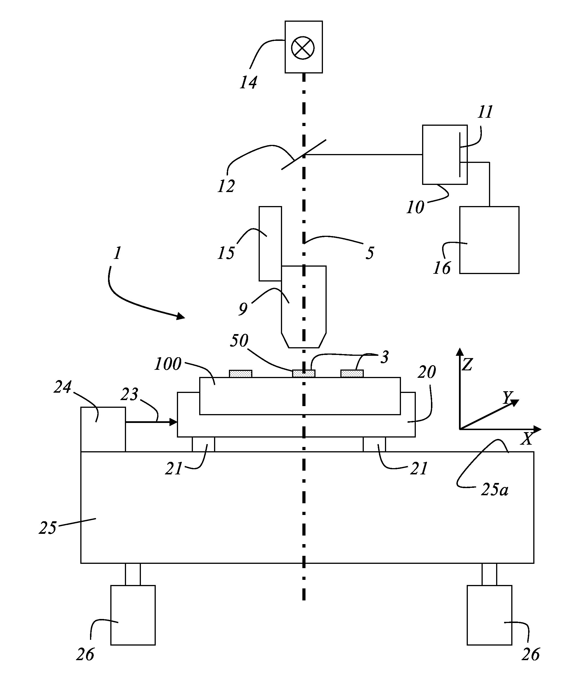
The present invention provides a method for accurately measuring the position of defects on objects, particularly EUV mask blanks, with high accuracy and high sampling rate. The method involves using a coordinate measuring machine that uses a laser light source and a detector array to illuminate and capture images of the object. The captured images are then analyzed to determine the position of any defects. The invention also provides a coordinate measuring machine that can measure the position of phase defects on objects with an uncertainty of less than 30 nm. The accuracy of the position measurement is important for ensuring the proper operation and performance of the object being measured.

Problems solved by technology

The limitation of current inspection systems is that the inspection systems are designed for high speed applications and do not have the accurate stage interferometer and environmental control required for sub-30 nm defect location accuracy.
), however these systems cannot provide accurate enough position information in order to use the above mentioned software and higher (<30 nm) defect location accuracy is requested from leading customers.
However, the difficulty of EUV mask manufacture has compelled the industry to look for compromise solutions by which some yield limiting phase defects will be accepted.
This software is only feasible if the location of all detected phase defects is well known with an accuracy of 30 nm or less.

Method used


Image

  • System and method for determining the position of defects on objects, coordinate measuring unit and computer program for coordinate measuring unit
  • System and method for determining the position of defects on objects, coordinate measuring unit and computer program for coordinate measuring unit
  • System and method for determining the position of defects on objects, coordinate measuring unit and computer program for coordinate measuring unit

Examples


Embodiment Construction

[0052]In the following description, numerous specific details are set forth in order to provide a thorough understanding of the present invention. The present invention may be practiced without some or all of these specific details. In other instances, well known process operations have not been described in detail to not unnecessarily obscure the present invention. While the invention will be described in conjunction with the specific embodiments, it will be understood that it is not intended to limit the invention to the embodiments.

[0053]Identical reference numerals refer to the same elements throughout the various figures. Furthermore, only reference numerals necessary for the description of the respective figure are shown in the figures. The shown embodiments represent only examples of how the invention can be carried out. This should not be regarded as limiting the invention.

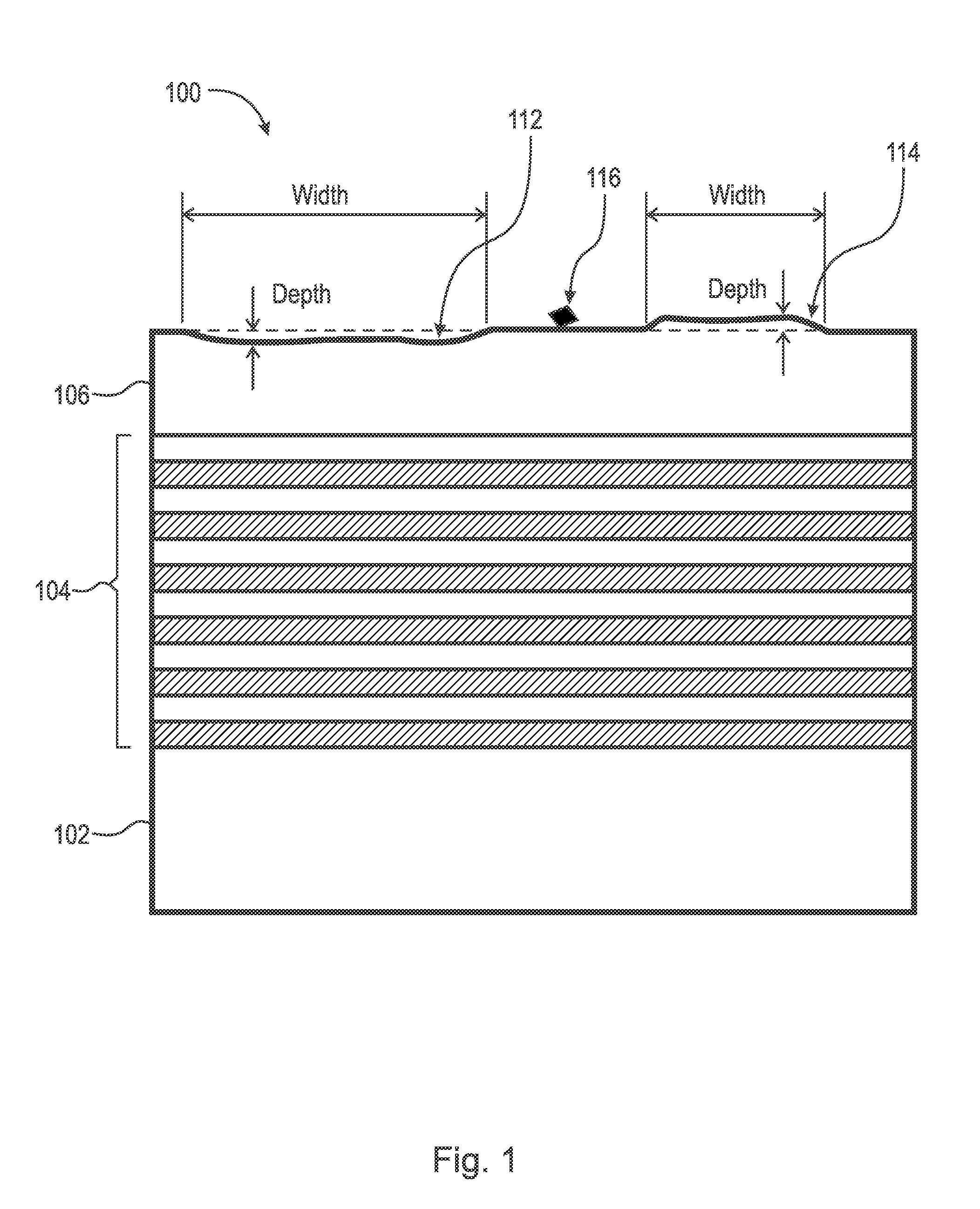
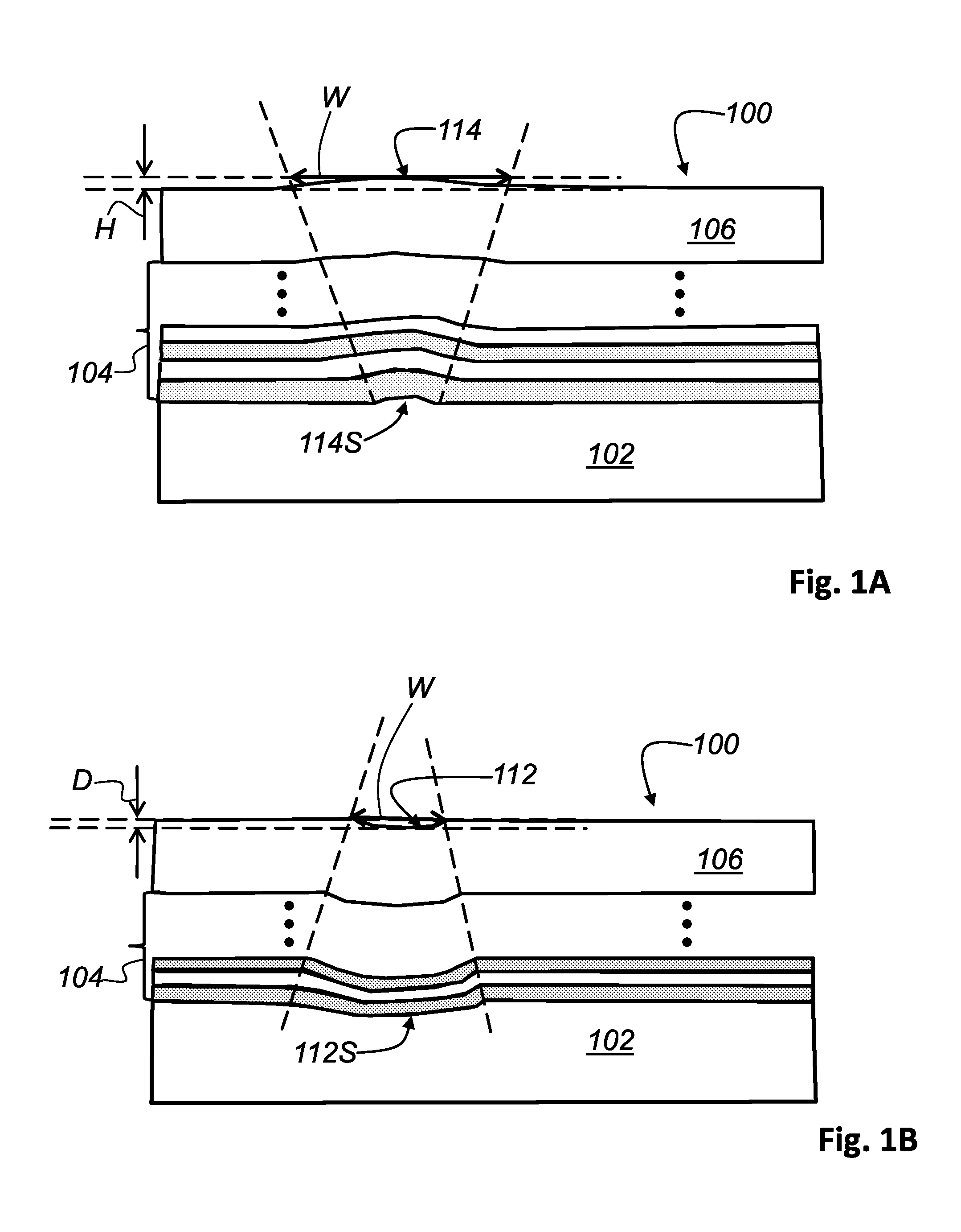
[0054]FIG. 1 is a side view schematic representation of an unpatterned object 100, which is a EUV mask ...


PUM

PropertyMeasurementUnit
wavelengthaaaaaaaaaa
heightaaaaaaaaaa
wavelengthsaaaaaaaaaa

Abstract

A system, a method and a coordinate measuring machine is disclosed for determining the position of defects on objects. An interface is provided so that alignment and coordinate information from the inspection device can be sent to the coordinate measuring machine. A special illumination and detection arrangement is used with a plurality of optical elements in order to obtain a signal from defects on the unpatterned object. The light source of the illumination and detection arrangement is a laser light source for providing a partially coherent light beam. A computer calculates from the data provides by the detector array and the alignment and coordinate information of the object from the inspection device a position of the defect on the object.

Description

CROSS-REFERENCE TO RELATED APPLICATIONS[0001]This application is a Continuation of International Patent Application Serial No. PCT / US2014 / 37916, filed on May 13, 2014, which application claims priority of U.S. Provisional Patent Application No. 61 / 834,987, filed on Jun. 14, 2013, which applications are incorporated herein by reference.FIELD OF THE INVENTION[0002]The present invention relates to a system for determining the position of defects on objects.[0003]The present invention also relates to a method for determining the position of defects on objects.[0004]Additionally, the present invention relates to a coordinate measuring machine for determining the position of defects on objects.[0005]Furthermore, the invention relates to a computer program for a coordinate measuring machine in order to determine a position of at least one defect on an object.BACKGROUND OF THE INVENTION[0006]The U.S. Pat. No. 7,903,259 discloses a device for determining the position of a structure on an obj...

Claims


Application Information

Patent Timeline
Patent Type & Authority Applications(United States)
IPC IPC(8): G01B11/00G01N21/88
CPCG01B11/005G01N21/8806G01N2201/0691G01N2201/0697G01N2201/06113G03F1/22G03F1/84
Inventor ROETH, KLAUS-DIETERDANESHPANAH, MOHAMMAD M.BUETTNER, ALEXANDERSEZGINER, APOWAGNER, MARK
Owner KLA TENCOR TECH CORP
Learn More