Device and Method For Harvesting Energy

Inactive Publication Date: 2015-08-13
CHIMAMKPAM EMMANUEL F C
View PDF4 Cites 3 Cited by
  • Summary
  • Abstract
  • Description
  • Claims
  • Application Information

AI Technical Summary

Benefits of technology

[0011]The present invention is a miniature device for synchronous harvesting of multiple sources of energy, including anatomical motions, acoustical energy, and stray electromagnetic signals across a wide range of frequencies at wide bandwidths for the production of electrical power. In one embodiment, the device comprises a housing, a mechanical spring engaged with the housing between a static and dynamic state and a first magnet engaged with the mechanical spring. The device further comprises a conductive grid freely moveable within a cavity of the housing. The device further comprises a composite structure comprising a fixed magnet and a piezoelectric material. The composite structure is engaged with the grid and in communication with the first magnet. The first magnet and the

Problems solved by technology

However, these type of conventional vibration energy harvesters have not been successful as a battery replacement in most electronic devices because of mechanical and electrical constraints.
This is a huge waste disposal issue and degrades the environment.
Vibration energy harvesting is promising but faces many difficulties.
The rules always lead to a narrow frequency response and make it difficult to tune the frequencies at which energies are harvested.
Narrow bandwidth limits an energy harvesting device to one specific frequency only, leadi

Method used


Image

  • Device and Method For Harvesting Energy
  • Device and Method For Harvesting Energy
  • Device and Method For Harvesting Energy

Examples


Example

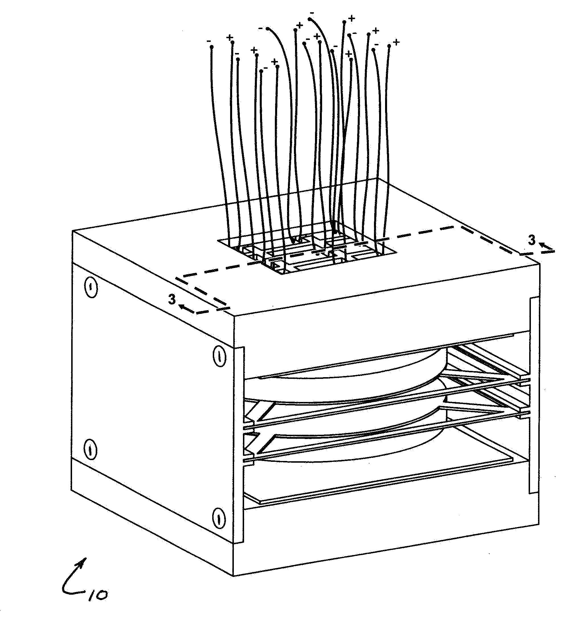
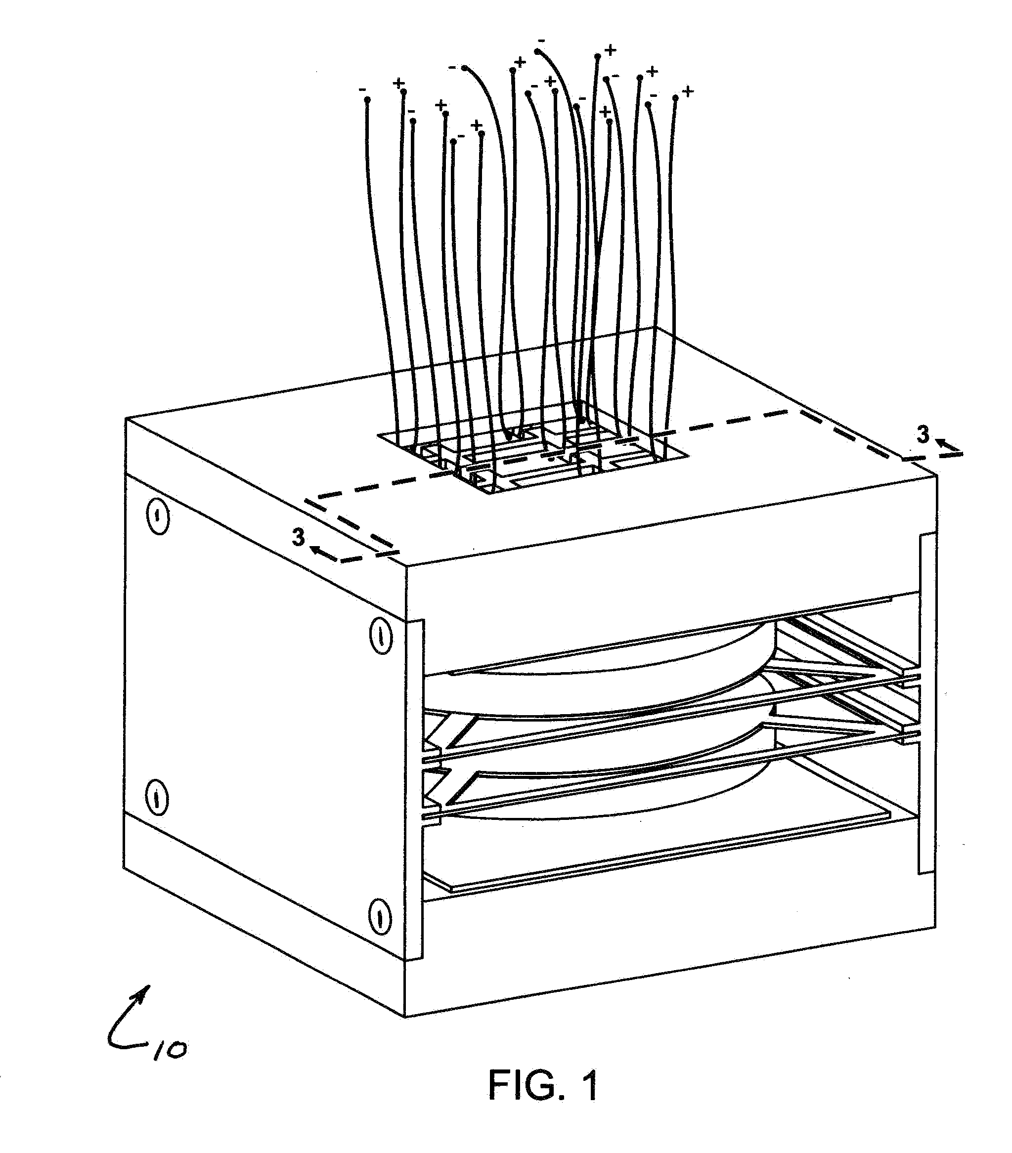
[0052]Referring to FIG. 1, where an energy harvesting device 10 according to the present invention is shown. Device 10 collects energy from movements, noise, sound, and stray electromagnetic signals and generates electricity. Movements can be generated from many sources such as transportation systems (for example, cars, trains, bicycles, and airplanes); infrastructures (for example, buildings, bridges, tunnels, and airports); anatomical (for example, human, animals, and plants); and machinery (for example, industrial plants, vacuum pumps, milling machines, and heavy duty vehicles). Noises can be of thermal, electromagnetic perturbations, colored noise, and white noise. Device 10 captures energy sources in the form of sinusoid, random noise, impulse and their different combinations. In the embodiment shown, device 10 has an overall length of 31 mm, a width of 24 mm, and a height of 24 mm. Unlike conventional energy harvesting devices, device 10 captures energy from movements, noise, ...


PUM


Abstract

A miniature energy harvesting device for producing electricity from acoustical energy, stray electromagnetic energy, noise and from energy of different anatomical motions. The device comprises a housing, a mechanical spring engaged with the housing between a static and dynamic state and a first magnet engaged with the mechanical spring. The device further comprises a conductive grid freely moveable within a cavity of the housing. The device further comprises a composite structure comprising a fixed magnet and a piezoelectric material. The composite structure is engaged with the grid and in communication with the first magnet. The first magnet and the fixed magnet apply a force upon the piezoelectric material when the mechanical spring is in the static state to produce a base voltage. Excitation of the mechanical spring causes the piezoelectric material to generate an alternating voltage output having a peak voltage greater than the base voltage.

Description

CROSS-REFERENCE TO RELATED APPLICATIONS[0001]This application claims priority to U.S. Provisional Application Ser. No. 61 / 937,330 filed on Feb. 7, 2014, now pending, which is hereby incorporated into this specification by reference in its entirety.BACKGROUND OF THE INVENTION[0002]Harvesting energy from sounds, human motions, stray electromagnetic signals, vibrating machines, etc. offers many advantages over other sources of energy such as solar cells that generate electrical energy from sunlight but require batteries when sunlight is not present. In the early 1900s, energy harvesters collected energy from vibration and were used as direct battery replacements in flash lights. This type of vibration energy harvester and others like it are based upon principles of transduction where a strong magnet is passed into and out of a tightly coiled wire thereby inducing a current in the coiled wire. In recent conventional devices, energy is stored in a capacitor which can be recharged several...

Claims


Application Information

Patent Timeline
IPC IPC(8): H02N2/18
CPCH02N2/188H02N2/186
Inventor CHIMAMKPAM, EMMANUEL F. C.
Owner CHIMAMKPAM EMMANUEL F C
Why Eureka
Try Eureka