Audio-power converter

a converter and audio technology, applied in the field of audio-power converters, can solve the problem of limited use of accessories that consume less than 10 mw

Inactive Publication Date: 2015-04-23
LOGUE SAMEER
View PDF0 Cites 0 Cited by
  • Summary
  • Abstract
  • Description
  • Claims
  • Application Information

AI Technical Summary

Benefits of technology

[0004]The present disclosure includes an apparatus and method by which the traditional limitations of audio signal conversion are overcome to allow such circuits to provide useful power.

Problems solved by technology

Though the audio output per channel from the said devices could be of the order of 30 mW to 55 mW per channel, use is limited to accessories that consumes less than about 10 mW considering losses in conversion to higher usable voltage from the 0.15-0.4V peak-to-peak at the audio output.

Method used


Image

  • Audio-power converter
  • Audio-power converter
  • Audio-power converter

Examples


Embodiment Construction

[0016]While the making and using of various embodiments of the present disclosure are discussed in detail below, it should be appreciated that the present disclosure provides many applicable inventive concepts, which can be embodied in a wide variety of specific contexts. The disclosure is primarily described and illustrated hereinafter in conjunction with various embodiments of the presently-described systems and methods. The specific embodiments discussed herein are, however, merely illustrative of specific ways to make and use the disclosure and do not limit the scope of the disclosure.

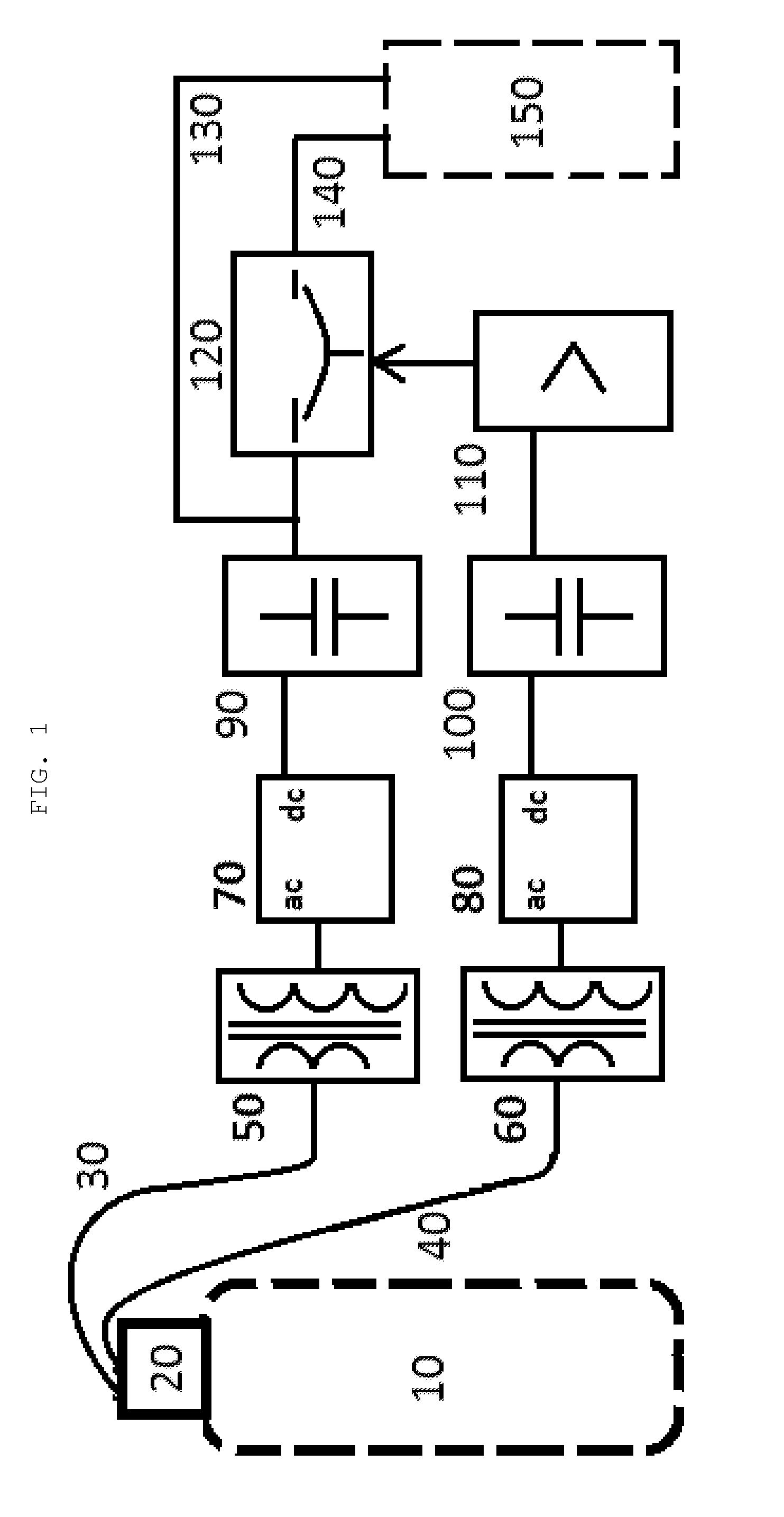
[0017]FIG. 1 shows a block diagram of the preferred embodiment of the invention, which comprises the electrical components between the Mobile Computer 10 and the Accessory 150. The whole circuit may be enclosed within an accessory, in that case 150 shows the main part of the accessory other than the power supply.

[0018]The Headphone Connector 20 accepts signals from the Mobile Computer, conveyed by ...


PUM


Abstract

An apparatus and method for converting audio signals to power supply signals that includes a step-up transformer, rectifier, and energy storage device on each channel, and uses information on one channel to control the output voltage sources.

Description

TECHNICAL FIELD OF THE INVENTION[0001]The present disclosure relates to the use of mobile computers and other electronic to charge and sequence power in their accessories.BACKGROUND OF THE INVENTION[0002]Method for powering an accessory device using the audio output ports of devices like Walkman and computers have existed for some time. Though the audio output per channel from the said devices could be of the order of 30 mW to 55 mW per channel, use is limited to accessories that consumes less than about 10 mW considering losses in conversion to higher usable voltage from the 0.15-0.4V peak-to-peak at the audio output.[0003]The electronics industry still seeks a useful approach to audio signal conversion that is not limited to such small power needs.SUMMARY OF THE INVENTION[0004]The present disclosure includes an apparatus and method by which the traditional limitations of audio signal conversion are overcome to allow such circuits to provide useful power.[0005]The method here aims ...

Claims


Application Information

Patent Timeline
Patent Type & Authority Applications(United States)
IPC IPC(8): H02J1/10
CPCH02J1/102H02J1/10H02J5/00G06F1/266
Inventor CHOLAYIL, SAMEER
Owner LOGUE SAMEER
Why Eureka
Try Eureka