Rapid prototyping apparatus for producing three-dimensional ceramic object

a three-dimensional ceramic and rapid prototyping technology, applied in the direction of additive manufacturing, applying layer means, manufacturing tools, etc., can solve the problems of more delicate and consistent quality of ceramic objects, and achieve the effects of reducing labor costs, improving quality, and speeding up speed

Active Publication Date: 2015-08-20
MICROJET TECH
View PDF3 Cites 28 Cited by
  • Summary
  • Abstract
  • Description
  • Claims
  • Application Information

AI Technical Summary

Benefits of technology

[0009]An object of the present invention provides a rapid prototyping apparatus for producing

Problems solved by technology

In addition, the quality of the ceramic

Method used


Image

  • Rapid prototyping apparatus for producing three-dimensional ceramic object
  • Rapid prototyping apparatus for producing three-dimensional ceramic object
  • Rapid prototyping apparatus for producing three-dimensional ceramic object

Examples


Embodiment Construction

[0019]The present invention will now be described more specifically with reference to the following embodiments. It is to be noted that the following descriptions of preferred embodiments of this invention are presented herein for purpose of illustration and description only. It is not intended to be exhaustive or to be limited to the precise form disclosed.

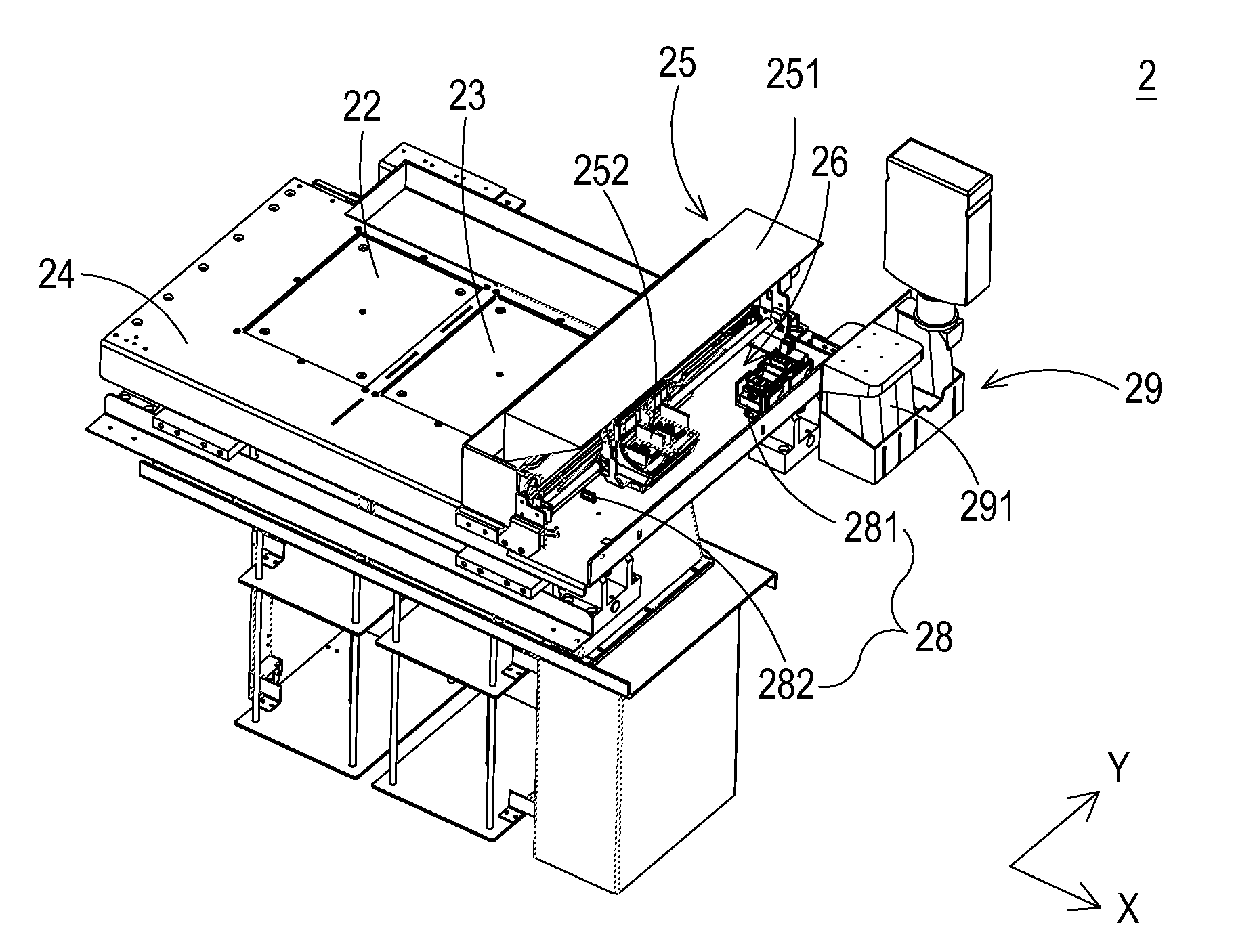
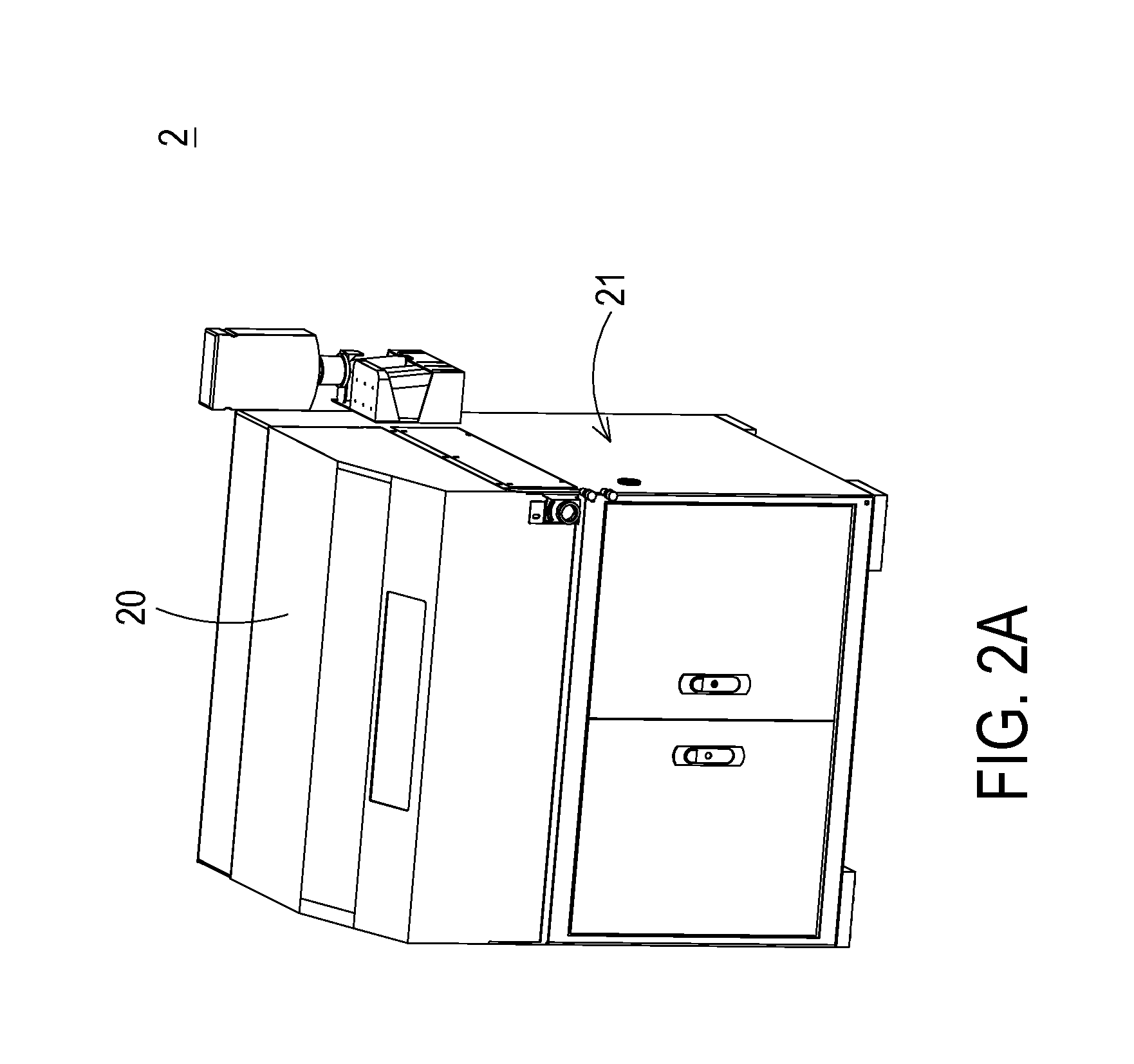
[0020]FIG. 2A is a schematic perspective view illustrating the outer appearance of a rapid prototyping apparatus for producing a three-dimensional ceramic object according to an embodiment of the present invention. FIG. 2B is a schematic perspective view illustrating the inner structure of the rapid prototyping apparatus of FIG. 2A.

[0021]As shown in FIG. 2A, the rapid prototyping apparatus 2 comprises an upper cover 20 and a main body 21. The main body 21 is covered by the upper cover 20. Consequently, a sealed space (not shown) is defined within the upper cover 20. Since the rapid prototyping operation is performed within the se...


PUM

PropertyMeasurementUnit
Distanceaaaaaaaaaa
Distanceaaaaaaaaaa
Speedaaaaaaaaaa

Abstract

A rapid prototyping apparatus includes a construction platform, a movable platform, a printing module, a cleaning and maintenance module, a construction material spreading element, a heater and a heat shield. A construction chamber is formed in the construction platform. The movable platform and the construction platform are movable relative to each other. The printing module is installed on the movable platform, and includes at least one printhead unit. The cleaning and maintenance module is installed on the movable platform. The construction material spreading element is installed on the movable platform for spreading a ceramic construction material to the construction chamber. After the ceramic construction material is spread in the construction chamber, the construction material is heated by the heater. After the printhead unit performs a printing operation, the printhead unit is cleaned and maintained by the cleaning and maintenance module.

Description

FIELD OF THE INVENTION[0001]The present invention relates to a rapid prototyping apparatus, and more particularly to a rapid prototyping apparatus for producing a three-dimensional ceramic object.BACKGROUND OF THE INVENTION[0002]Generally, ceramic objects are produced by a series of complicated steps, including a step of forming pottery slurry, a step of molding clay, an air drying step and a high temperature sintering step. As known, these steps are labor-intensive and time-consuming. Moreover, since these steps are manually performed and controlled, some drawbacks may occur. For example, since the step of forming pottery slurry is manually done, the quality of the raw material cannot be uniformly controlled. In other words, the finished ceramic objects may have inconsistent quality. After the step of forming pottery slurry, the step of molding clay is performed. During the step of molding clay, the extents of fineness of the finished ceramic objects are varied depending on the exp...

Claims


Application Information

Patent Timeline
IPC IPC(8): B29C67/00
CPCB28B1/001B29L2009/00B33Y30/00B29C64/209B29C64/232B29C64/35B29C64/357
Inventor SHI, KWO-YUANHUANG, KE-MING
Owner MICROJET TECH
Why Eureka
Try Eureka