Two-part wheel spider with profile spokes

a technology of wheel spiders and spokes, which is applied in the direction of disc wheels, spoked wheels, non-metallic wheel bodies, etc., can solve the problems of high manufacturing cost, limited design freedom of wheel spiders, and adverse effect on the strength of end products

Inactive Publication Date: 2015-08-20
THYSSENKRUPP CARBON COMPONENTS
View PDF11 Cites 12 Cited by
  • Summary
  • Abstract
  • Description
  • Claims
  • Application Information

AI Technical Summary

Benefits of technology

[0006]An object is therefore to provide a wheel construction that offers a great freedom in designing t...

Problems solved by technology

This has an adverse effect on the strength of the end product.
The need for a circumferential contour disadvantageously leads to limitations in the freedom of design of the wheel spiders.
This manuf...

Method used


Image

  • Two-part wheel spider with profile spokes
  • Two-part wheel spider with profile spokes
  • Two-part wheel spider with profile spokes

Examples


exemplary embodiment 1

According to FIG. 1, FIG. 2 (a-c), FIG. 3, FIG. 4 (a-c), FIG. 5

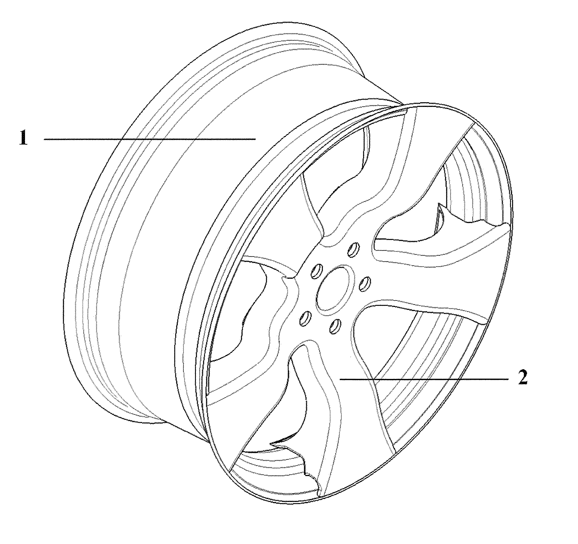
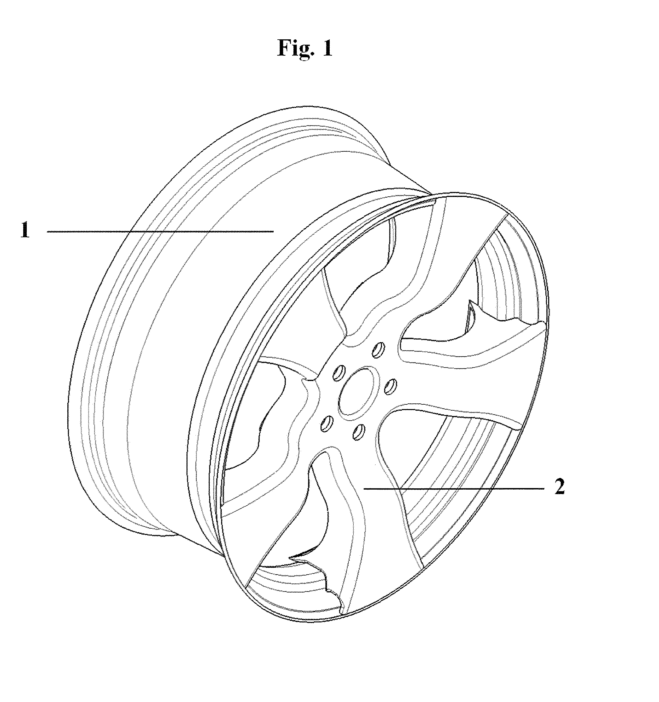
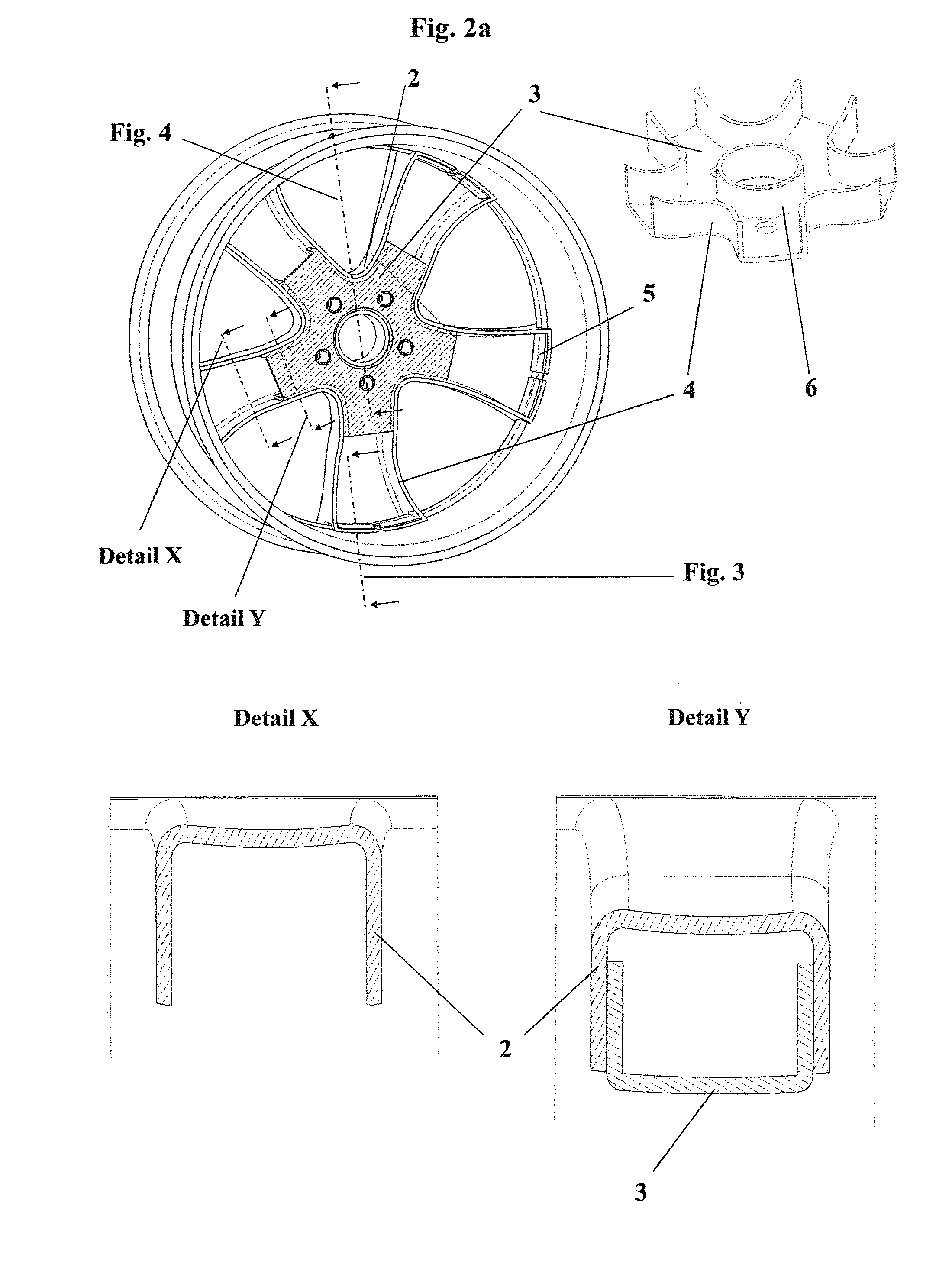
[0039]In the first exemplary embodiment, the wheel spider is composed of two separate molded parts (2, 3), which form the spoke segments as well as the wheel hub. The spoke segments of the first molded part (2) are characterized on the vehicle side by an open cross section., Detail X shows the cross section of a spoke, the one in the area in which the molded part 2 does not close the opening in the U-shaped cross section of the first molded part (2). It can be recognized in detail Y how this opening is covered in another area by the second molded part (3), which meshes with same in a positive-locking manner and likewise has a U-shaped cross section. The spokes are integrated axially and radially by means of a positive-locking connection (FIG. 3) in the textile structure of the rim well (1). The undercut is formed by the lateral, axially directed areas (4) of the spoke cross section, which are folded over toward the centr...

exemplary embodiment 2

According to FIG. 6, FIG. 7, FIG. 8 (a-b), FIG. 9

[0041]The wheel spider likewise consists of two fiber composite molded parts in this exemplary embodiment. The open cross section of the spokes is located now on the side facing away from the vehicle, so that the connection of the spoke segments to the rim well can take place over a large area. Furthermore, the spokes are connected with the drop base of the rim well by an undercut positive-locking connection, and the undercut straps of the spoke segments (5) can be integrated on or in the textile braided structure of the rim well (FIGS. 8a, 8b). This molded part (2) assumes at the same time the function of the wheel hub connection surface of the wheel. The second molded part (3) is positioned by means of corresponding spacing segments and thus closes the open cross section of the spoke segment completely.

[0042]The two molded parts (2, 3) are connected with one another in a positive-locking manner via the borders of the spoke profiles ...

exemplary embodiment 3

According to FIG. 10, FIG. 11, FIG. 12

[0043]This exemplary embodiment differs from the preceding ones in that the wheel spider is composed of a metallic load application element (9) and a molded part made of fiber composite (2). The molded part with the spoke segments and with the wheel hub connection surface is connected, as was described in the exemplary embodiment 2, with the rim well. The metallic load application element (9) is characterized by a circumferential wave contour, as a result of which the element used to receive the wheel bolt elements is integrated between the axially directed areas of the spoke segments and the hub centering of the molded part such that it is secured against rotation (FIG. 12). The contact surfaces may be used for an additional bonded connection here.


PUM


Abstract

A wheel includes a rim having a rim base and a two-part wheel spider. The wheel spider includes two molded parts. The first molded part forms the spokes having an open cross-section and is joined to the second molded part. The spokes of the first molded part are completely or partially closed along the profile length by the second molded part. The wheel spider is preferably integrated in the rim in an interlocking manner. The rim and the two-part wheel spider can consist of metal, but in particular preferably of composite fiber material.

Description

CROSS REFERENCE TO RELATED APPLICATIONS[0001]This application is a United States National Phase Application of International Application PCT / EP2013 / 071204 filed Oct. 10, 2013 and claims the benefit of priority under 35 U.S.C. §119 of German Patent Application DE 10 2012 022 148.7 filed Nov. 6, 2012, the entire contents of which are incorporated herein by reference.FIELD OF THE INVENTION[0002]The present invention pertains to a wheel spider with profile spokes, which is composed of at least two individual parts, which mesh with one another in a positive-locking manner.BACKGROUND OF THE INVENTION[0003]A number of constructions are known, which use wheel spiders made of fiber composites. These are often made initially during the manufacture as disk wheel spiders and are provided with recesses after the consolidation, for example, by means of CNC milling. The continuous course of the fibers is naturally interrupted in the process. This has an adverse effect on the strength of the end pr...

Claims


Application Information

Patent Timeline
IPC IPC(8): B60B3/08B60B3/12B60B3/10B60B1/14B60B1/12
CPCB60B1/06B60B3/10B60B5/02B60B7/065B60B3/08B60B1/12B60B1/14B60B3/12B60B2900/311
Inventor DRESSLER, MICHAELWERNER, JENSKOHLER, CHRISTIANBARTSCH, ANDREMAKE, SANDRO
Owner THYSSENKRUPP CARBON COMPONENTS
Why Eureka
Try Eureka