Gas turbine engine

Inactive Publication Date: 2015-08-20
ROLLS ROYCE PLC
View PDF6 Cites 6 Cited by
  • Summary
  • Abstract
  • Description
  • Claims
  • Application Information

AI Technical Summary

Benefits of technology

The invention improves the performance of a fan containment system by engaging two fan track liner panels. This helps to control the fan blade trajectory and prevent damage to the surrounding components. The design also makes maintenance work easier.

Problems solved by technology

These lighter fan blades have similar impact energy per unit area as an ice sheet, which makes it more difficult to devise a casing arrangement that will resist the passage of ice and yet not interfere with the trajectory of a released fan blade.
The step creates a barrier to a released fan blade, so there is a concern that the released fan blade may skip over the hook and avoid containment.
However, the use of adhesive creates problems for both assembly and on-wing repair.

Method used


Image

  • Gas turbine engine
  • Gas turbine engine
  • Gas turbine engine

Examples


Embodiment Construction

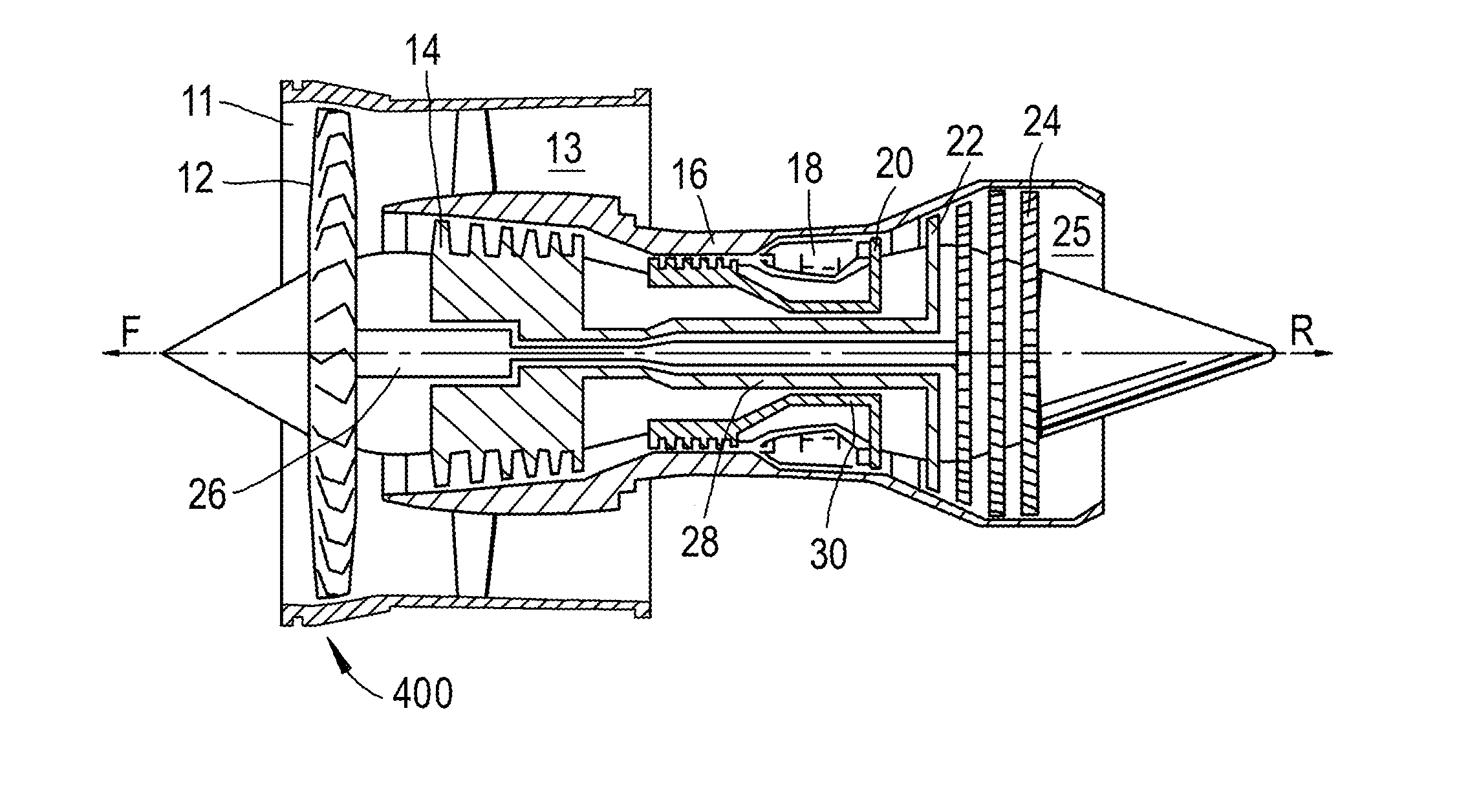
[0058]With reference to FIG. 4 a bypass gas turbine engine is indicated at 10. The engine 10 comprises, in axial flow series, an air intake duct 11, fan 12, a bypass duct 13, an intermediate pressure compressor 14, a high pressure compressor 16, a combustor 18, a high pressure turbine 20, an intermediate pressure turbine 22, a low pressure turbine 24 and an exhaust nozzle 25. The fan 12, compressors 14, 16 and turbines 18, 20, 22 all rotate about the major axis of the gas turbine engine 10 and so define the axial direction of the gas turbine engine.

[0059]Air is drawn through the air intake duct 11 by the fan 12 where it is accelerated. A significant portion of the airflow is discharged through the bypass duct 13 generating a corresponding portion of the engine thrust. The remainder is drawn through the intermediate pressure compressor 14 into what is termed the core of the engine 10 where the air is compressed. A further stage of compression takes place in the high pressure compress...


PUM


Abstract

A fan containment system for fitment around an array of radially extending fan blades mounted on a hub in an axial gas turbine engine, including: a fan case having an annular casing element for encircling an array of fan blades and an annular fan track liner lining a radially inner side of the casing element, including a first fan track liner panel positioned circumferentially adjacent a second fan track liner panel. An engagement arrangement engages the first fan track liner panel to the second, extending along at least a portion of adjacent sides of the liner panels, and is configured and the liner panels are shaped such that axial movement of the first fan track liner panel by a distance less than the length of the engagement arrangement, being measured in a direction parallel to the adjacent sides of the liner panels, disengages the first liner panel from the second.

Description

FIELD OF INVENTION[0001]The present disclosure relates to a fan containment system, a casing assembly, a fan and / or a gas turbine engine.BACKGROUND[0002]Turbofan gas turbine engines (which may be referred to simply as ‘turbofans’) are typically employed to power aircraft. Turbofans are particularly useful on commercial aircraft where fuel consumption is a primary concern. Typically a turbofan gas turbine engine will comprise an axial fan driven by an engine core. The engine core is generally made up of one or more turbines which drive respective compressors via coaxial shafts. The fan is usually driven directly off an additional lower pressure turbine in the engine core.[0003]To satisfy regulatory requirements, such engines are required to demonstrate that if part or all of a fan blade were to become detached from the remainder of the fan, that the detached parts are suitably captured within the engine containment system.[0004]The fan is radially surrounded by a fan casing. It is kn...

Claims


Application Information

Patent Timeline
IPC IPC(8): F01D21/04
CPCF05D2220/36F01D21/045F01D25/246F05D2250/294F05D2260/36Y02T50/60
Inventor REED, JULIAN MARK
Owner ROLLS ROYCE PLC
Why Eureka
Try Eureka