
Inductive current absolute position sensor by using code rail type staff and read out head

An absolute position and sensor technology, which is applied in the use of electric/magnetic devices to transmit sensing components, the use of electric devices, and the conversion of sensor outputs, etc., can solve problems such as failure to provide a sensing system, and achieve high accuracy and low manufacturing costs. Effect

Inactive Publication Date: 2006-07-05
MITUTOYO CORP
View PDF9 Cites 0 Cited by
  • Summary
  • Abstract
  • Description
  • Claims
  • Application Information

AI Technical Summary

Problems solved by technology

Sensing systems that provide at least these five benefits have not been available until now

Method used


Image

  • Inductive current absolute position sensor by using code rail type staff and read out head
  • Inductive current absolute position sensor by using code rail type staff and read out head
  • Inductive current absolute position sensor by using code rail type staff and read out head

Examples


Embodiment Construction

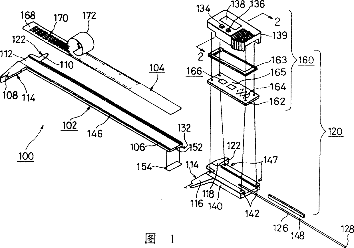
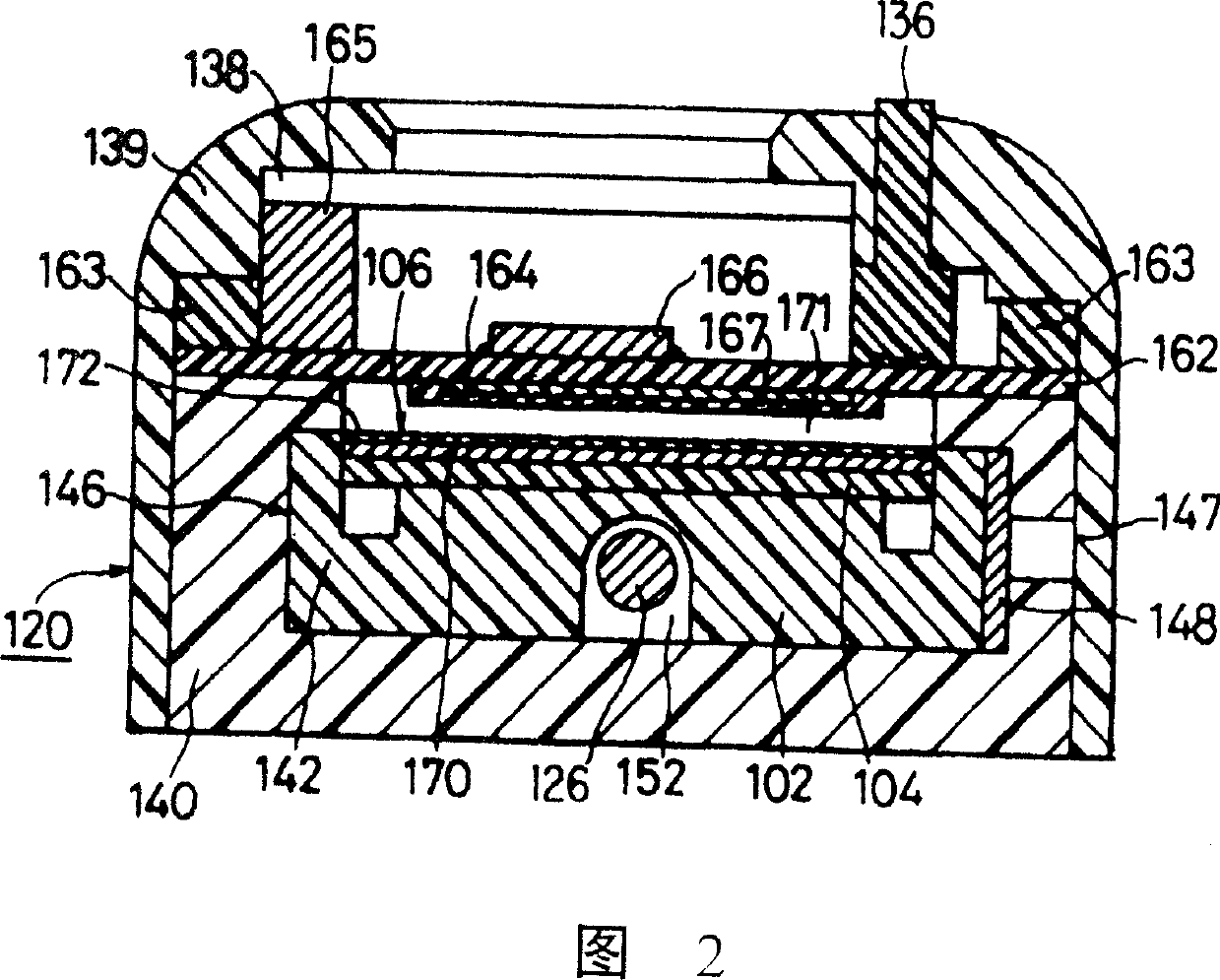
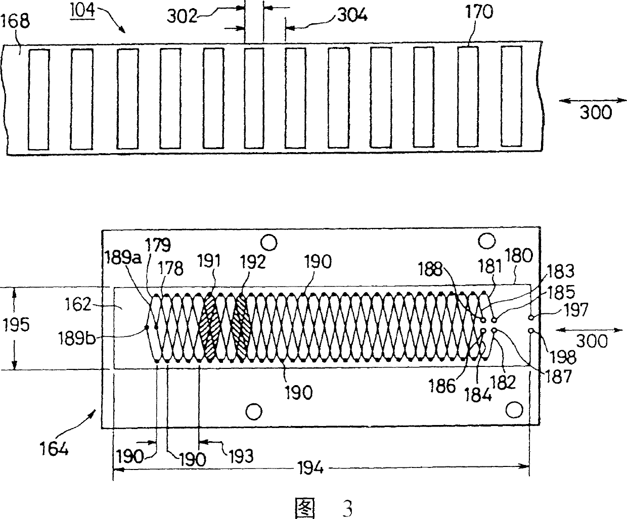
[0093] For convenience and clarity, the working principle, design factors, and configuration of the sensor winding of the present invention are described with reference to the incremental measurement type sensor used in the caliper shown in FIGS. 1-3. The basic description of the working principle of the incremental measurement sensor winding is suitable for understanding and designing the constituent windings used in the absolute sensor of the present invention.

[0094] As shown in FIG. 1, the inductive caliper 100 includes a long beam 102. The long beam 102 is a solid or semi-rigid rod with a generally rectangular cross-section. A groove 106 is formed on the upper surface of the long beam 102. The elongated measuring rule 104 is firmly engaged in the groove 106 of the long beam 102. The groove 106 is formed in the long beam 102 at a depth equal to the thickness of the measuring rule 104. Therefore, the upper surface of the measuring rule 104 and the upper edge of the long beam ...


PUM


Abstract

A high precision inductance type of absolute position sensor is provided with two components which can move reciprocally. The sensor comprises a code track sensor which is composed of an emitter coil and at least a receiver coil; each receiver coil comprises n positive and negative polarity balance pairs which extend along a measure axis; the code track is provided with a plurality of magnetic flux modulator regions which are distributed along the measure axis. The coupling of the emitter coil induction and the balance pair induction is modulated according to the relative position between a reading head and a ruler. Each pair of the neighboring magnetic flux modulator regions forms a series of code elements; m neighboring code elements form a special code word; each code word limits the absolute position of the reading head relative to the ruler to a first differentiation rate.

Description

Technical field [0001] The invention relates to an absolute position electronic sensor, more specifically a sensor using a plurality of inductively coupled sensor windings. Background technique [0002] Many different motion or position sensing systems are currently available. Most of these sensors can be sensitive to linear, rotational or angular motion. Optical sensors usually have a scanning device and a glass ruler with grating. The scanning device usually includes a light source, a condenser lens that collimates the light of the light source, a scanning plate of a scale grating, and a photodetector. The glass ruler moves relative to the scanning device. The scale lines on the glass ruler alternately coincide with the lines or intervals of the scale grating of the scanning plate, producing periodic light intensity fluctuations. The photodetector converts periodic light intensity fluctuations into electrical signals, which are then processed to determine the position. Optical ...

Claims


Application Information

Patent Timeline
IPC IPC(8): G01B7/02G01D5/20G01R27/26G01B7/00G01B3/20G01B7/14G01B7/30G01D5/245H03M1/22H03M1/24
CPCG01D5/2053
Inventor 卡尔G·马斯里利斯尼尔斯I·安德姆金W·阿瑟顿
Owner MITUTOYO CORP
Learn More